Calculating method and calculating application of forms of debris flow siltation behind silt arresters
A technology for sand dams and debris flow, applied in water conservancy projects, water conservancy engineering equipment, buildings, etc., can solve the problems of not considering the nature of debris fluid, the error between calculation results and actual values, etc., and achieve the effect of effective and simple calculation methods
- Summary
- Abstract
- Description
- Claims
- Application Information
AI Technical Summary
Problems solved by technology
Method used
Image
Examples
Embodiment 1
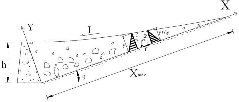
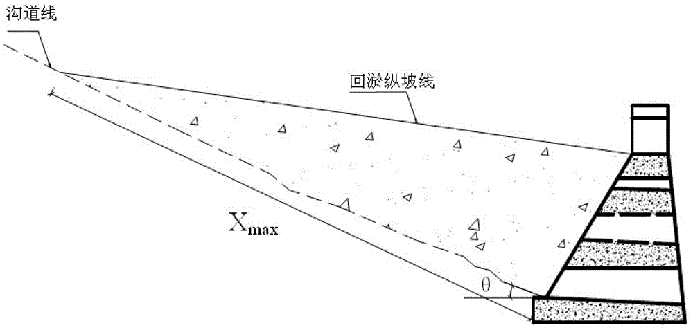
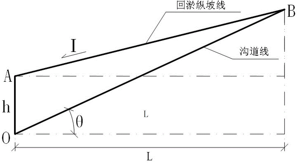
[0037] Such as figure 1 , figure 2 , image 3 shown. A debris flow ditch in Mianzhu is located on the left bank of the Mianyuan River, with a drainage area of 1.36km 2 , the highest point in the region is 1987m above sea level, the lowest point is 810m above sea level, and the relative height difference is 1177m; the slope of the ditch bed is 412‰, the length of the main ditch is 2.59km, and the width of the watershed is between 330m and 990m. At 30°~70°, it is partly cliff landform. After the earthquake, large-scale mudslides broke out in the river basin many times. After rushing out of the ditch, the mudslides directly entered the Mianyuan River at the mouth of the ditch. Distant rivers formed mudslides and dammed lakes.
[0038] In order to alleviate the debris flow disaster, it is planned to build a sand control dam in the main ditch of the debris flow. The effective height h of the sand control dam is 12.0m, and the width of the channel is 15.0m. The height of th...
Embodiment 2
[0044] Such as figure 1 shown. A debris flow ditch in Yingxiu is located on the inner side of Duwen Road on the G213 line, on the left bank of the Minjiang River. The ditch is 1.24km long and has a drainage area of 0.52km 2 , the average gradient is 722‰, the highest point elevation is 1885m, the lowest point elevation is 943m, and the relative height difference is 942m. After the earthquake, three large-scale mudslides broke out in the ditch, which blocked and silted Duwen Road on the G213 line, causing a large number of vehicles to be stranded and greatly affecting the normal operation of traffic. In order to reduce debris flow disasters, it is planned to arrange a cascaded sand dam group consisting of 10 sand dams in the middle reaches of the debris flow ditch. The effective height h of each sand dam is determined through field investigation, as shown in Table 1. Next, determine the distance between the adjacent dam bodies of the cascade sand retaining dam.
[0045] Fi...
Embodiment 3
[0053] Such as figure 1 shown. The same place as in Embodiment 1 will not be described again, and the difference is that:
[0054] In order to reduce debris flow disasters, a sand dam and a submerged sill are planned to be built in the debris flow tributary ditch. The submerged sill is located at 13.7m in the upstream reservoir of the proposed sand control dam, and the submerged sill is a restricted silting point. The allowable maximum dam height of the sand control dam is determined below.
[0055] Through the measurement and calculation of the large-scale topographic map, it is determined that the slope of the debris flow ditch in this section is θ=23°. internal friction angle of debris fluid The distance xl=13.7m between the limited silting point and the sand check dam, and the channel slope θ=23° are substituted into the allowable maximum sand check dam height formula The maximum allowed height of the sand check dam is calculated to be 5.14m. Accordingly, the effect...
PUM
 Abstract
Description
Claims
Application Information
 - R&D
- Intellectual Property
- Life Sciences
- Materials
- Tech Scout
- Unparalleled Data Quality
- Higher Quality Content
- 60% Fewer Hallucinations
Browse by: Latest US Patents, China's latest patents, Technical Efficacy Thesaurus, Application Domain, Technology Topic, Popular Technical Reports.
© 2025 PatSnap. All rights reserved.Legal|Privacy policy|Modern Slavery Act Transparency Statement|Sitemap|About US| Contact US: help@patsnap.com


