Fluorescence microscopy imaging system and method for monitoring neural network
A neural network and microscopic imaging technology, applied in the field of imaging systems, can solve the problems of long scanning time, inability to detect for a long time, and inability to achieve fast imaging of neural samples, and achieve the effect of short time
- Summary
- Abstract
- Description
- Claims
- Application Information
AI Technical Summary
Problems solved by technology
Method used
Image

Examples
Embodiment 1
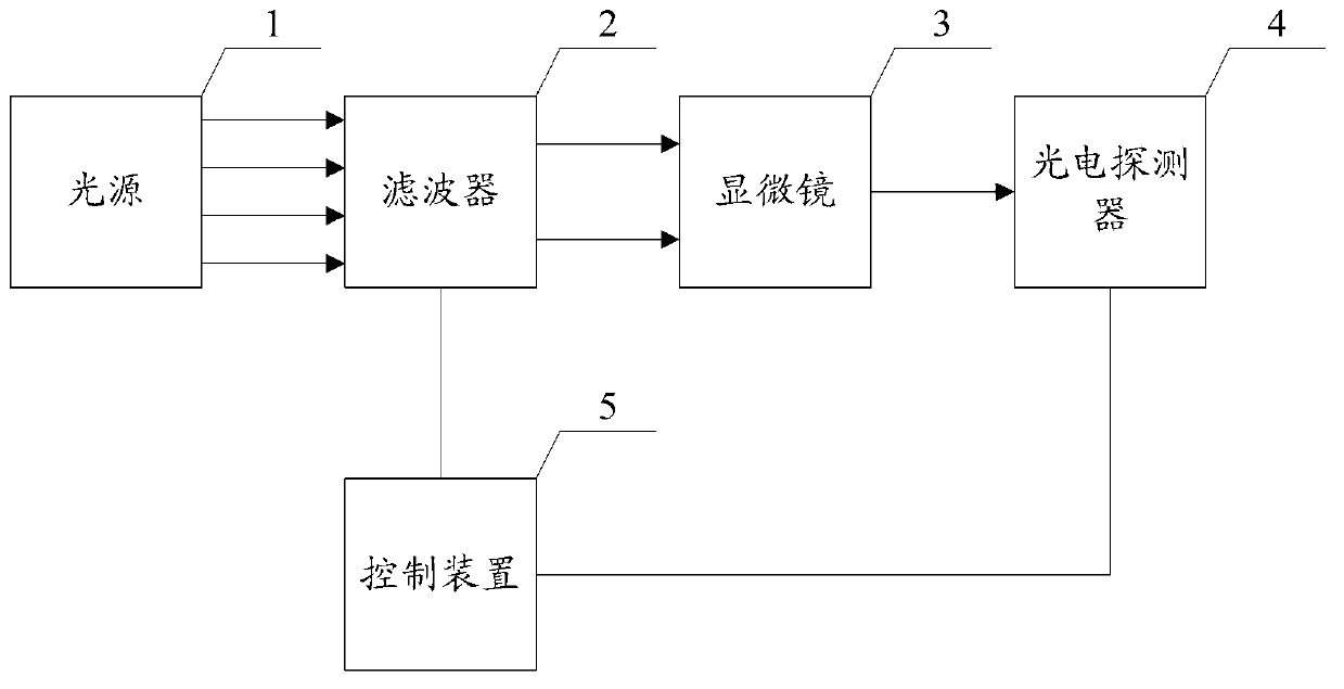
[0033] An embodiment of the present invention provides a fluorescence microscopy imaging system for monitoring neural networks, see figure 1 , the system includes: a light source 1 , a filter 2 , a microscope 3 , a photodetector 4 , and a control device 5 .
[0034] Wherein, the filter 2 is used to adjust the wavelength and light passing time of the light passing through the filter 2 under the control of the control device 5 . The photodetector 4 is used for wide-field imaging under the control of the control device 5 . The filter 2 , the microscope 3 and the photodetector 4 are sequentially located on the light path of the light source 1 . The control device 5 is electrically connected to the filter 2 and the photodetector 4 respectively. figure 1 Middle arrows indicate light propagation paths, and solid lines indicate electrical connections.
[0035] Specifically, the microscope 3 includes an objective lens and a stage for carrying a nerve sample marked with a fluorescent...
Embodiment 2
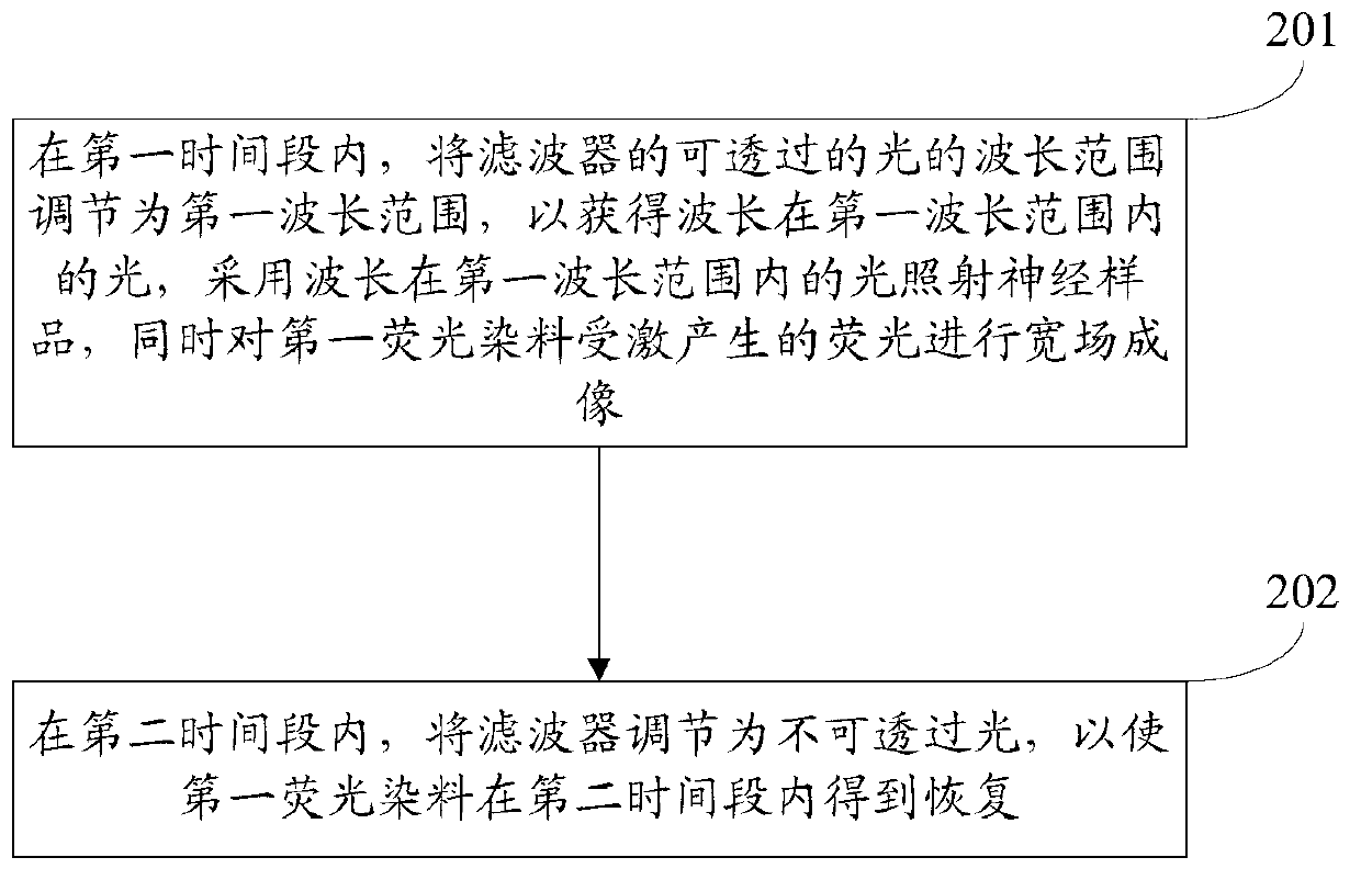
[0045] An embodiment of the present invention provides a fluorescent imaging method for monitoring neural networks, which is suitable for monitoring neural samples marked with fluorescent dyes. The fluorescent dyes labeled with neural samples may include one or more types. This embodiment will use a The present invention will be described by taking a fluorescent dye (first fluorescent dye) as an example. In this embodiment, the first fluorescent dye is the calcium fluorescent dye Oregon Green488BAPTA-2, AM, and the central wavelength of the excitation of Oregon Green488BAPTA-2, AM is 496 nm. see figure 2 , the method includes:
[0046] Step 201: During the first time period, adjust the wavelength range of the light that can pass through the filter to the first wavelength range, so as to obtain light with a wavelength in the first wavelength range, and use a light with a wavelength in the first wavelength range The neural sample is illuminated with light while widefield imag...
Embodiment 3
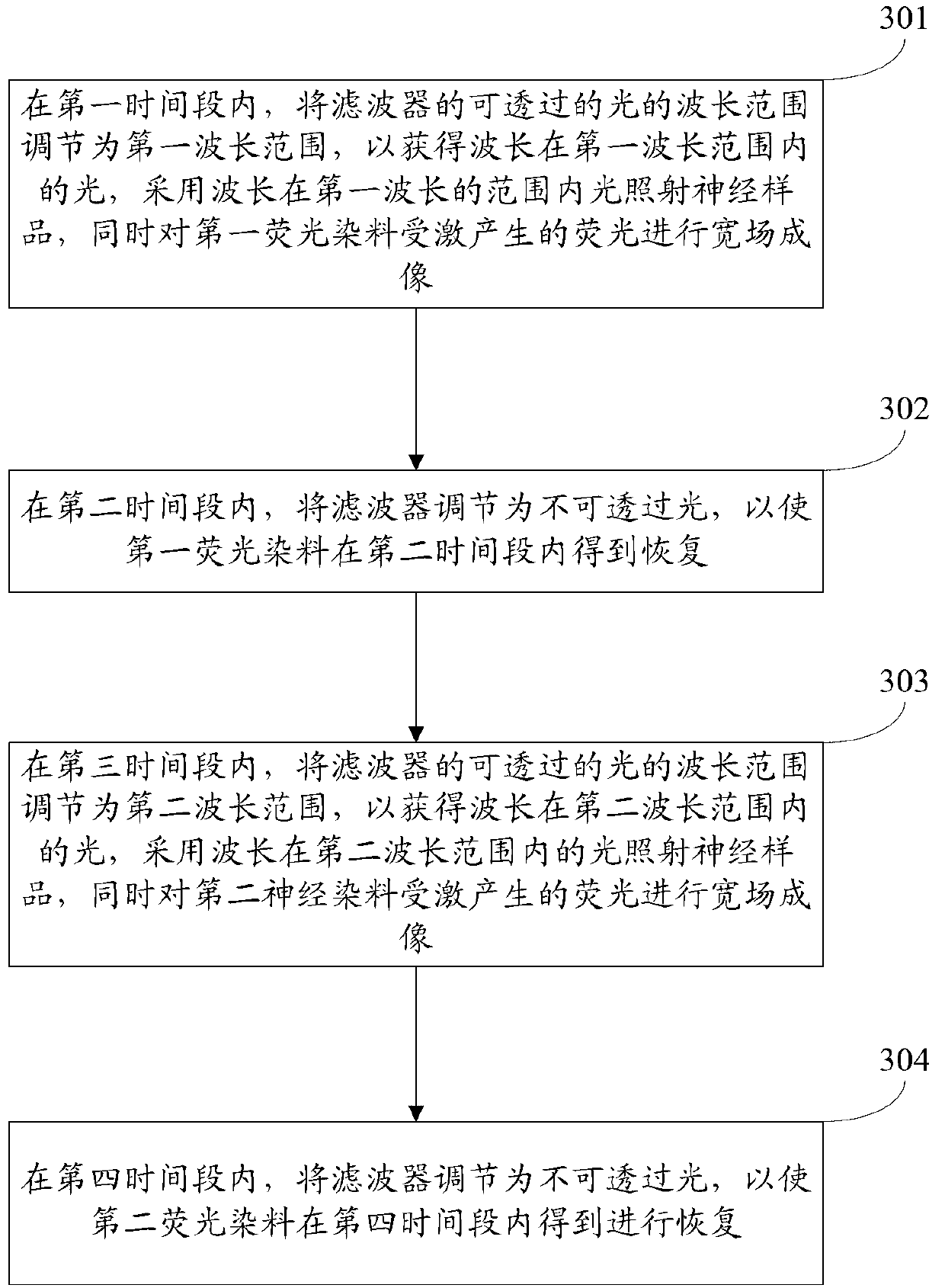
[0057] An embodiment of the present invention provides a fluorescent imaging method for monitoring neural networks, which is suitable for monitoring neural samples marked with fluorescent dyes. The fluorescent dyes labeled with neural samples may include one or more types. This embodiment will use two The present invention will be described by taking fluorescent dyes (first fluorescent dye and second fluorescent dye) as examples. In this embodiment, the first fluorescent dye is calcium fluorescent dye Oregon Green488BAPTA-2, AM, which excites Oregon Green488BAPTA-2, and the wavelength corresponding to the center frequency of AM is 496nm, and the second fluorescent dye is calcium fluorescent dye Oregon Green488Rhod-2, AM, excited Oregon Green488Rhod-2, the center wavelength of AM is 552nm. see image 3 , the method includes:
[0058] Step 301: During the first time period, adjust the wavelength range of the light that can pass through the filter to the first wavelength range,...
PUM
 Abstract
Description
Claims
Application Information
 - R&D Engineer
- R&D Manager
- IP Professional
- Industry Leading Data Capabilities
- Powerful AI technology
- Patent DNA Extraction
Browse by: Latest US Patents, China's latest patents, Technical Efficacy Thesaurus, Application Domain, Technology Topic.
© 2024 PatSnap. All rights reserved.Legal|Privacy policy|Modern Slavery Act Transparency Statement|Sitemap