Orientation device

A technology of orientation and transmission, which is applied in nonlinear optics, instruments, optics, etc., can solve the problems of different bending degrees and different bending degrees of oriented hair 021, and achieve the effect of improving uniformity

Inactive Publication Date: 2015-07-22
BEIJING BOE OPTOELECTRONCIS TECH CO LTD
View PDF5 Cites 0 Cited by
  • Summary
  • Abstract
  • Description
  • Claims
  • Application Information

AI Technical Summary

Problems solved by technology

[0004] However, since a glass substrate 01 has only one orientation roller 02, the orientation of the glass substrate 01 by rolling will cause different bending degrees of the orientation hairs 021, and the orientation roller 02 in the prior art will be oriented to The bulk metal substrate area 011 of each array substrate (the metal substrate area 011 on the array substrate will be higher than the displayed effective area 012, and the different heights will also make the bending degree of the oriented hair 021 different), and the alignment roller 02 pairs When the bulk metal substrate region 011 is oriented, the bending degree of the oriented hair 021 is as follows figure 2 As shown, when the orientation roller 02 is oriented in the effective display area 012 except the bulk metal substrate area 011, the bending degree of the orientation hair 021 is as follows image 3 shown

Method used


Image

  • Orientation device
  • Orientation device
  • Orientation device

Examples


Embodiment Construction

[0043] The following will clearly and completely describe the technical solutions in the embodiments of the present invention with reference to the accompanying drawings in the embodiments of the present invention. Obviously, the described embodiments are only some, not all, embodiments of the present invention.

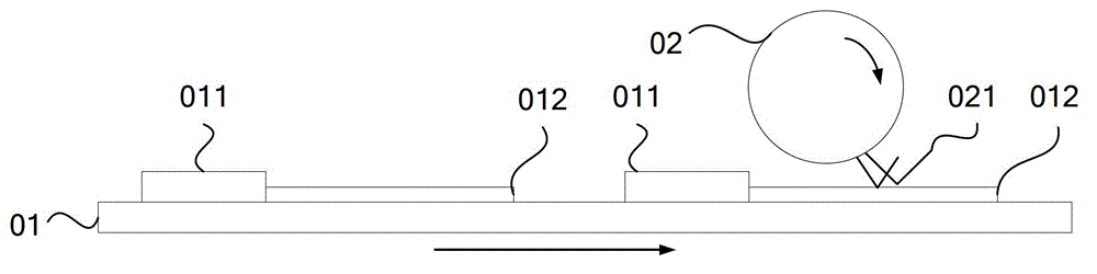
[0044] It should be noted that in the field of display, substrates are not limited to Figure 5 For the illustrated structure, for the convenience of description, the following embodiments are described with reference to the fifth-generation wire substrate (4*3) as an example. In addition, the alignment device provided by the present invention can not only align array substrates, but also align color filter substrates. For the convenience of description, the explanation below takes the alignment device to orient the array substrate as an example.

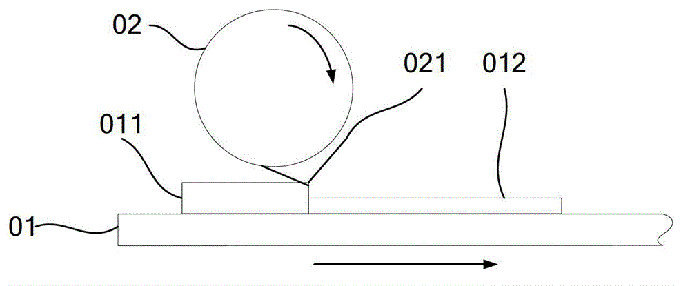
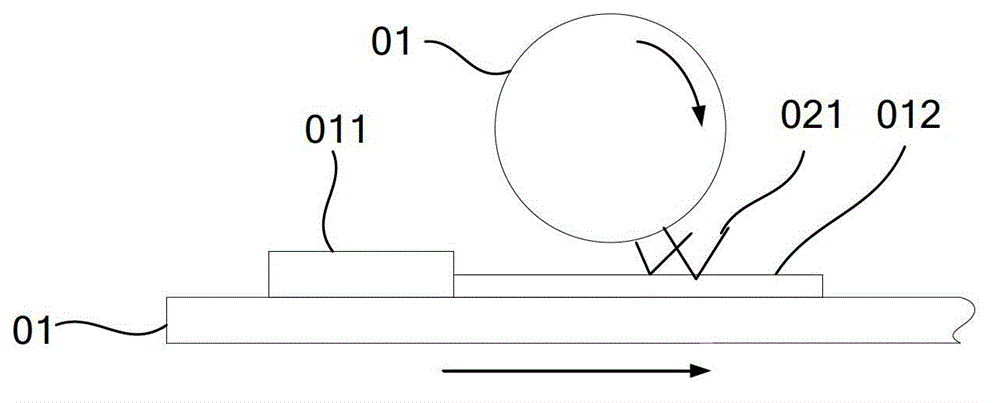
[0045] The structure of the orientation device provided by the invention is as Figure 5 As shown, the base station 1 ...


PUM

PropertyMeasurementUnit
widthaaaaaaaaaa

Abstract

An orientation apparatus comprises a base platform (1). The base platform (1) has a supporting surface for supporting a substrate (3). The orientation apparatus also comprises at least one friction plate (2) and a transmission apparatus (4). Orientation friction cloth (21) is attached to one surface, facing to the supporting surface, of each friction plate (2). A plane the hairs of the orientation friction cloth (21) are located on is a friction surface, and the friction surface is parallel to the supporting surface. The transmission apparatus (4) drives the friction plate (2) to perform frictional orientation on an active region of the substrate (3). The orientation apparatus improves the uniformity of an orientation process.

Description

technical field [0001] The invention relates to the technical field of liquid crystal display preparation technology, in particular to an alignment device. Background technique [0002] In the traditional TFT-LCD (Thin Film Transistor-Liquid Crystal Display, thin film transistor liquid crystal display device) manufacturing process, the metal pad area is coated, exposed, and etched to form metal wiring and identification marks. It is placed next to the active area of ​​the display screen with thin film transistor structure, so that the connecting leads can conduct the active area of ​​the display screen with thin film transistor structure. In this way, the area of ​​the metal substrate on the array substrate will be higher than the effective area of ​​the display. [0003] In the production process of liquid crystal display devices, there are generally multiple array substrates on a large glass substrate. The traditional alignment process such as figure 1 As shown, the orie...

Claims


Application Information

Patent Timeline
Patent Type & Authority Patents(China)
IPC IPC(8): G02F1/1337
CPCG02F1/133784
Inventor 李辉毛利军魏永辉李永涛
Owner BEIJING BOE OPTOELECTRONCIS TECH CO LTD
Why Eureka
Try Eureka