A new type of compressor self-limiting exhaust valve plate, exhaust valve plate assembly, compressor

An exhaust valve plate and compressor technology, applied in the field of compressors, can solve the problems of increased compressor noise, high-speed impact of valve plates and baffles, and increased impact degree, so as to reduce the number of parts, simplify the assembly process, and eliminate noise. the effect of

Active Publication Date: 2022-04-15
ZHUHAI GREE REFRIGERATION TECH CENT OF ENERGY SAVING & ENVIRONMENTAL PROTECTION
View PDF7 Cites 0 Cited by
  • Summary
  • Abstract
  • Description
  • Claims
  • Application Information

AI Technical Summary

Problems solved by technology

When the compressor exhausts, the high-pressure gas pushes the valve plate to open through the exhaust hole, resulting in a high-speed impact between the valve plate and the baffle plate. The reciprocating impact of the valve plate and the baffle plate often leads to fatigue fracture of the exhaust valve plate and compressor noise. intensification of
[0004] In addition, with the development trend of miniaturization of compressor structure and high-speed operation frequency, high-speed compressors have higher and higher requirements for exhaust valve components. Due to the high operating frequency of the compressor, the traditional exhaust valve plate reciprocates with the baffle If the degree is intensified, the risk of valve plate fracture is likely to occur, which will affect the reliability of the compressor. At the same time, the high-frequency flapping baffle will increase the noise of the compressor. It is an urgent need to improve the design of the current high-speed compressor.

Method used


Image

  • A new type of compressor self-limiting exhaust valve plate, exhaust valve plate assembly, compressor
  • A new type of compressor self-limiting exhaust valve plate, exhaust valve plate assembly, compressor
  • A new type of compressor self-limiting exhaust valve plate, exhaust valve plate assembly, compressor

Examples


Embodiment 1

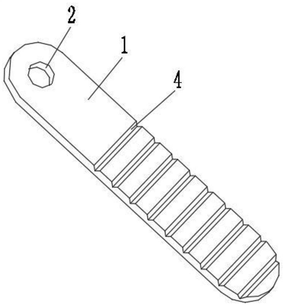
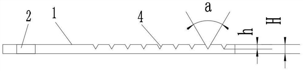
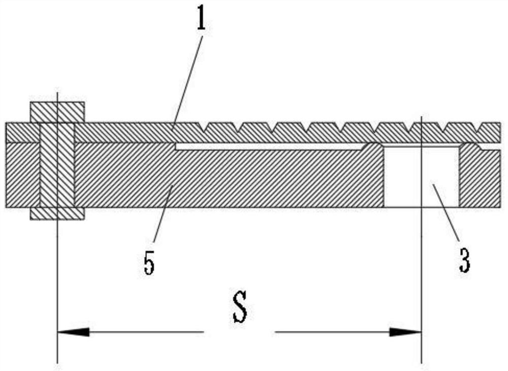
[0027] A new type of compressor self-limiting exhaust valve plate in this embodiment, such as Figure 1-4 As shown, including a valve plate 1, one end of the valve plate 1 is provided with a mounting hole 2 along the thickness direction of the valve plate 1, and the surface of the valve plate 1 facing away from the exhaust hole 3 is along the surface of the valve plate 1 There is at least one groove 4 crossing the valve plate 1 in the thickness direction. Install and fix the valve plate 1 on the valve seat 5 by opening an installation hole 2 along the thickness direction of the valve plate 1 at one end of the valve plate 1, and at the same time, through the surface of the valve plate 1 facing away from the exhaust hole 3 along the thickness of the valve plate 1 The groove 4 across the valve plate 1 is set in the direction of the compressor. When the compressor exhausts, the valve plate 1 is bent due to the impact of the gas, and the state of the valve plate 1 is determined by ...

Embodiment 2

[0035] This embodiment provides an exhaust valve assembly, such as Figure 1-4 As shown, the exhaust valve plate assembly uses the new self-limiting exhaust valve plate of the compressor described in Embodiment 1, and the valve plate 1 is fixed by opening a mounting hole 2 along the thickness direction of the valve plate 1 at one end of the valve plate 1. It is installed and fixed on the valve seat 5. At the same time, the groove 4 crossing the valve plate 1 is set on the surface of the valve plate 1 facing away from the exhaust hole 3 along the thickness direction of the valve plate 1. When the compressor exhausts, the valve plate 1 Bending occurs due to the impact of gas. At this time, the opening of the groove 4 will gradually decrease with the increase of the bending angle of the valve plate 1. When the bending angle of the valve plate 1 reaches a certain angle, the groove 4 will be completely closed, which can prevent the valve plate 1 continues to bend, so as to realize ...

Embodiment 3

[0038] This embodiment provides a compressor, which uses the exhaust valve plate assembly described in Embodiment 2, because the valve plate 1 is installed and fixed by opening an installation hole 2 at one end of the valve plate 1 along the thickness direction of the valve plate 1 On the valve seat 5, at the same time, by opening a groove 4 across the valve plate 1 along the thickness direction of the valve plate 1 on the surface of the valve plate 1 facing away from the exhaust hole 3, when the compressor is exhausted, the valve plate 1 will be exhausted due to gas At this time, the opening of the groove 4 will gradually decrease with the increase of the bending angle of the valve piece 1. When the bending angle of the valve piece 1 reaches a certain angle, the groove 4 will be completely closed, which can prevent the valve piece 1 from continuing to bend. Bending, so as to realize the automatic limit during the bending process of the valve piece 1, so the baffle can be remov...


PUM


Abstract

A novel compressor self-limiting exhaust valve plate, exhaust valve plate assembly, and compressor, relating to the technical field of compressors, the novel compressor self-limiting exhaust valve plate includes a valve plate, and one end of the valve plate is along the A mounting hole is opened in the thickness direction of the valve plate, and a groove crossing the valve plate is opened on the surface of the valve plate along the thickness direction of the valve plate. The valve plate is installed and fixed on the valve seat by opening a mounting hole at one end of the valve plate. Bending occurs due to the impact of gas. At this time, the opening of the groove will gradually decrease with the increase of the bending angle of the valve plate. When the bending angle of the valve plate reaches a certain angle, the groove will be completely closed, which can prevent the valve plate from continuing to bend, thereby Realize the automatic limit during the bending process of the valve plate, so the baffle plate can be removed, the noise caused by the reciprocating impact of the valve plate and the baffle plate and the fatigue fracture of the valve plate can be eliminated, and the number of parts of the exhaust valve plate assembly can be reduced at the same time.

Description

technical field [0001] The invention relates to the technical field of compressors, in particular to a novel compressor self-limiting exhaust valve plate, an exhaust valve plate assembly, and a compressor. Background technique [0002] The exhaust valve assembly is an important internal part of the compressor and is widely used in various compressors. Its reliability is very important. At the same time, the flapping of the traditional valve and baffle is one of the main sources of compressor noise . [0003] The traditional exhaust valve assembly is mainly composed of a valve plate, a baffle, a valve seat and rivets. The valve plate is a flexible sheet structure. During the exhaust stage, the valve plate is opened, and its lift is limited by the baffle; Finally, through the stiffness of the valve plate itself, the deformation is restored. When the compressor exhausts, the high-pressure gas pushes the valve plate to open through the exhaust hole, resulting in a high-speed i...

Claims


Application Information

Patent Timeline
Patent Type & Authority Patents(China)
IPC IPC(8): F04B39/10F04B39/14F04B39/00
CPCF04B39/102F04B39/14F04B39/0027F04B39/00
Inventor 罗发游任丽萍万鹏凯吴飞何洋
Owner ZHUHAI GREE REFRIGERATION TECH CENT OF ENERGY SAVING & ENVIRONMENTAL PROTECTION
Why Eureka
Try Eureka