
Pilot sequence structure in MIMO-OFDM/OQAM (Multi-input Multi-output-Orthogonal Frequency Division Multiplexing/Offset Quadrature Amplitude Modulation) system and channel estimation method
A pilot sequence and channel estimation technology, which is applied in the field of channel estimation, can solve the problem of multipath fading channel destroying the orthogonality characteristics, and achieve the effects of reducing correlation, eliminating channel multipath interference, and reducing linearity requirements
- Summary
- Abstract
- Description
- Claims
- Application Information
AI Technical Summary
Problems solved by technology
Method used
Image

Examples
Embodiment
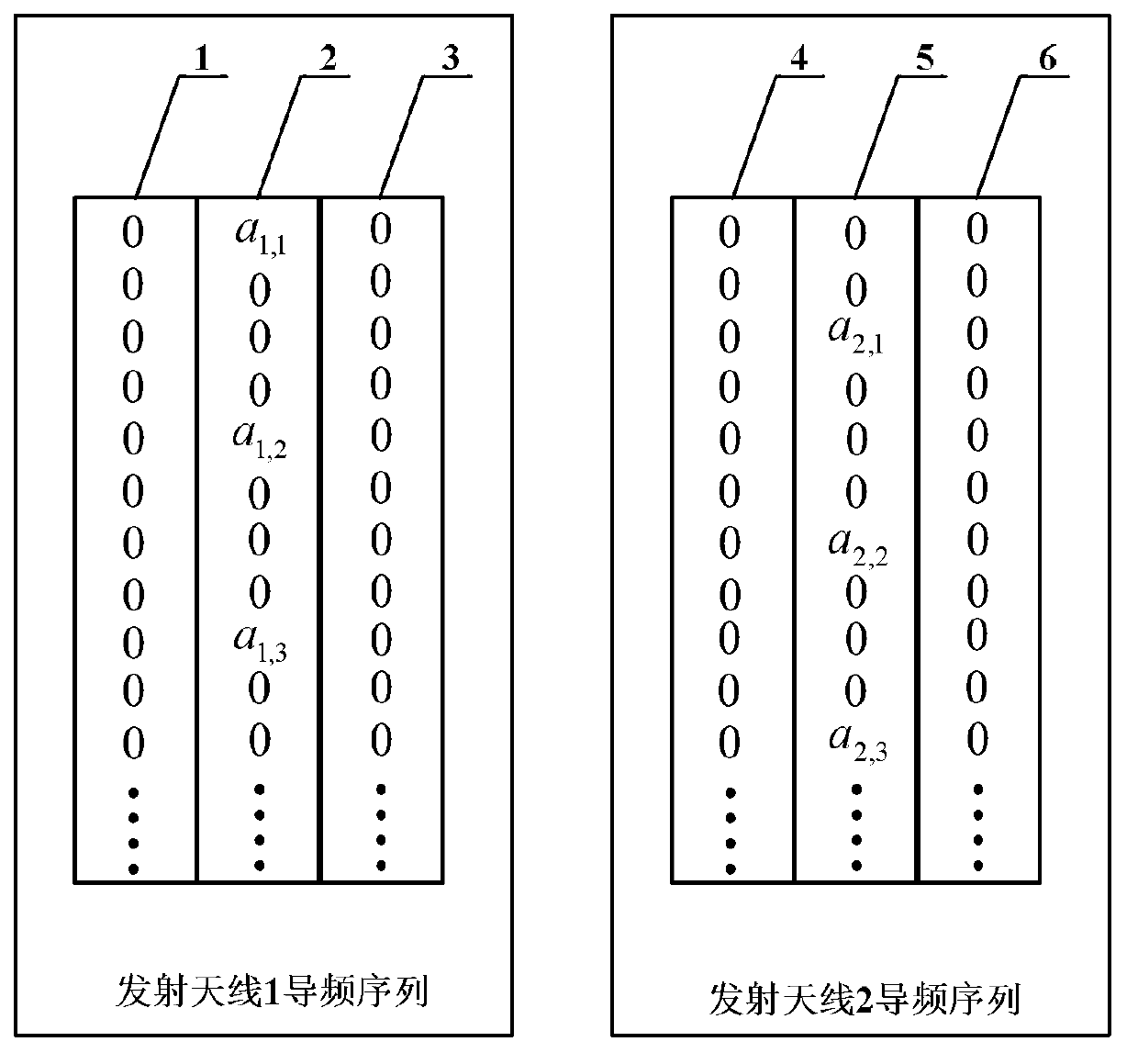
[0055] Figure 4 It is a schematic diagram of an embodiment of the pilot sequence structure in the MIMO-OFDM / OQAM system of the present invention. Such as Figure 4 As shown, the number of transmit antennas in this embodiment is N=2. In general, the set of candidate symbols Q can be {1,-1} or a set of complex signals with constant modulus. In this embodiment, the set of candidate symbols Q={1,-1}. In the pilot sequence corresponding to transmitting antenna 1, the first symbol sequence 7 and the third symbol sequence 9 are all zeros, and in the second symbol sequence 8, the first symbol a 1,1 =1, the fifth symbol a 1,2 =-1, the 9th symbol a 1,3 =-1, and so on, and the remaining symbols are zero. The 1st, 5th, 9th... symbols in the second symbol sequence 8 are used as pilot signals for channel estimation of the transmitting antenna 1 by the receiving end. In the pilot sequence corresponding to the transmitting antenna 2, the first symbol sequence 10 and the third symbol se...
PUM
 Abstract
Description
Claims
Application Information