Rotary heat engine

A heat engine and rotary technology, applied in the field of internal combustion engines and rotary engines, can solve problems such as inability to exceed performance, and achieve the effect of simple cooling, simple manufacturing or mass production, and high power.

Inactive Publication Date: 2013-09-04
纳克多·加西亚·罗德里格斯
View PDF5 Cites 5 Cited by
  • Summary
  • Abstract
  • Description
  • Claims
  • Application Information

AI Technical Summary

Problems solved by technology

None of the solutions to date have been able to exceed the performance of axially displaced conventional cylinder engines

Method used


Image

  • Rotary heat engine
  • Rotary heat engine
  • Rotary heat engine

Examples


Embodiment Construction

[0057] Looking at the previous figures, you can see various preferred examples of implementing the present invention according to the numbers used. The present invention includes the various components and elements shown and described.

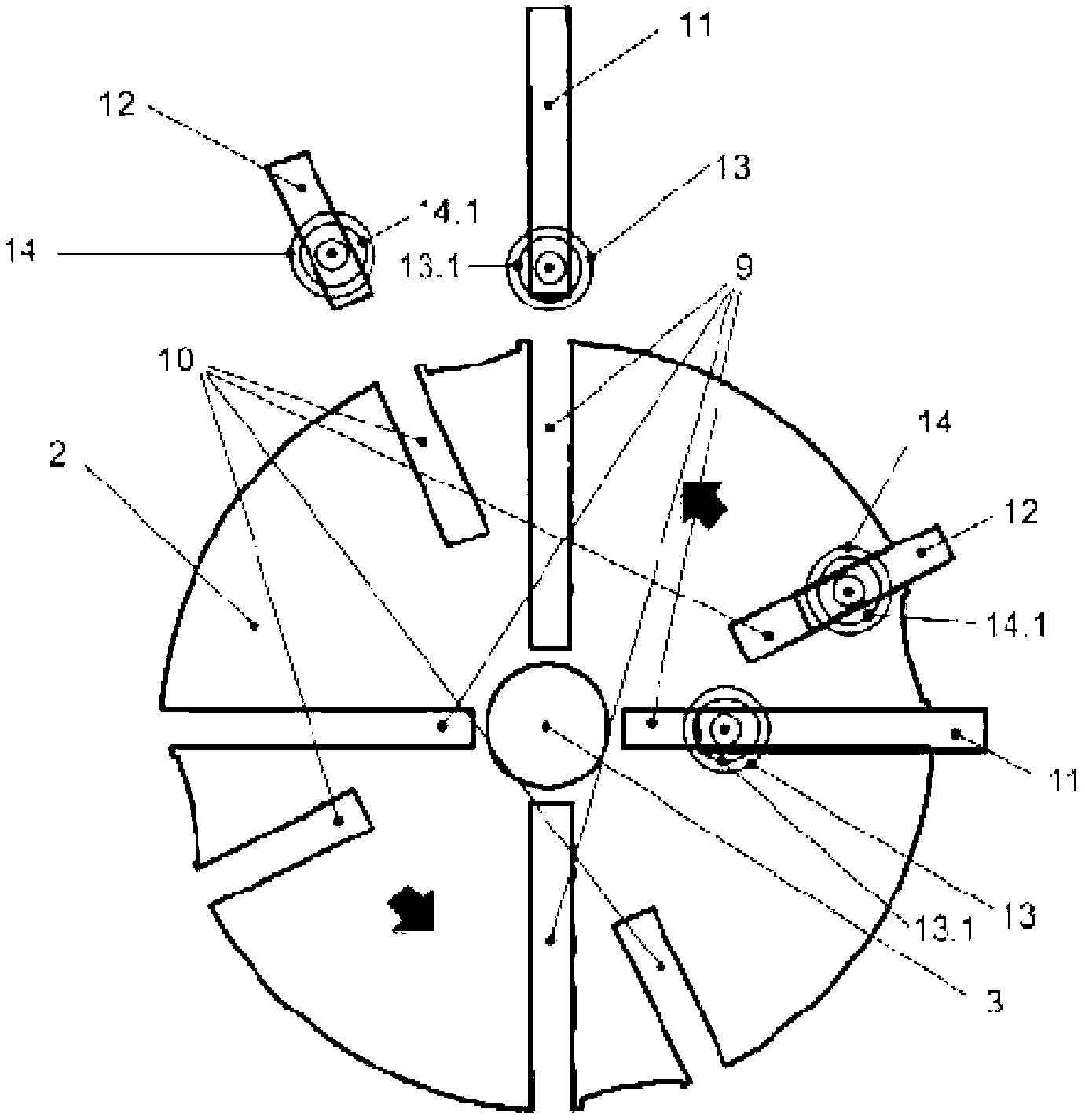
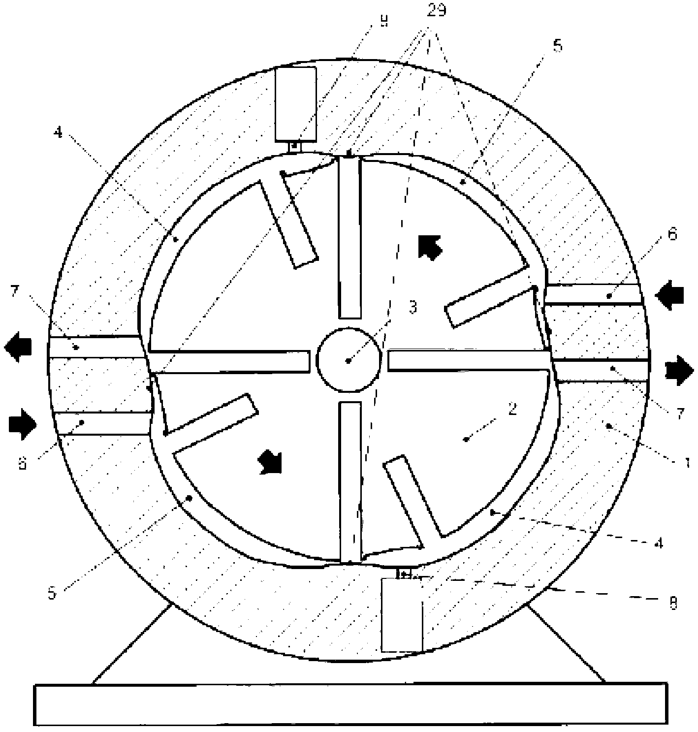
[0058] in figure 1 , The rotor 2 associated with the shaft 3 can be observed. The rotor has a cylindrical structure. There are opposing grooves on its periphery and some diametrically opposing slots 9 and 10, which define four regions.

[0059] These slots are drawn in a radial manner (pointing to the center of the rotor). However, the slots can also take other suitable forms, for example, positioned parallel to each other.

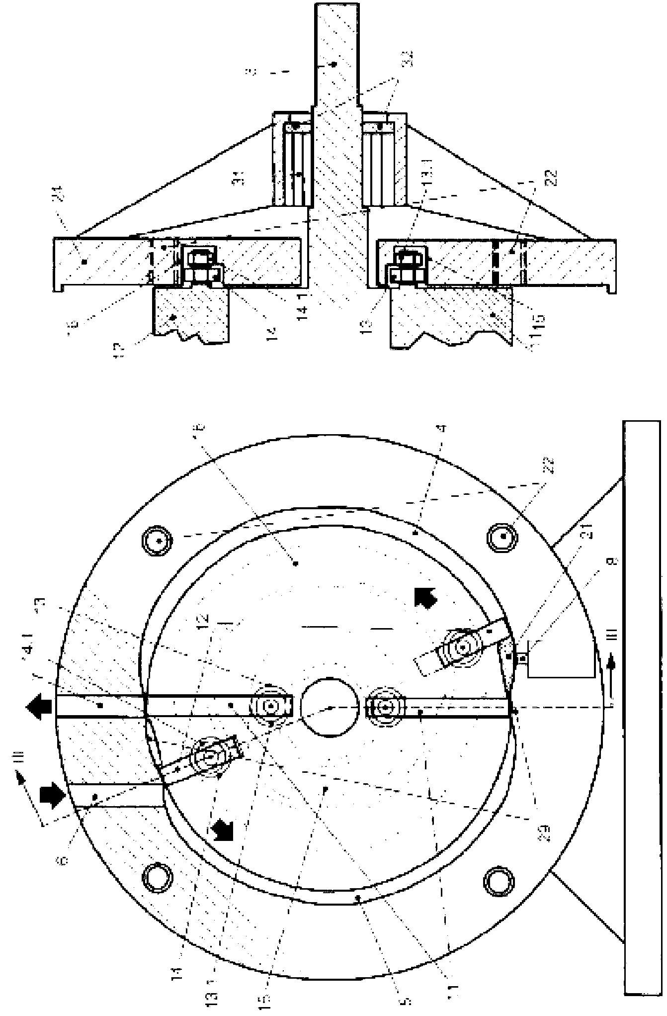
[0060] Each of the four regions defined in the rotor 2 has a slot 9 with a high depth and another slot 10 with a low depth. The pair of slots are respectively used to guide some blades 11 for feeding / compression and some blades 12 for expansion / discharge.

[0061] in image 3 with Figure 4 , The feeding / compression blades 11...


PUM


Abstract

The invention relates to a rotary heat engine that consists of a hollow stator, the inner surface of which has a series of opposite deformations, and also has a cylindrical rotor on the perimeter of which are opposite recesses, defining at least two quadrants or sections that define expansion and expulsion chambers and other admission and compression chambers, wherein each section surface of the rotor has two grooves along which blades slide, by means of bearings that run through guides in the covers of the engine, such that it results in an engine that produces several expansions per revolution, thus managing to perform nearly all the work of the expansions in each cycle, improving the performance of alternate cylinder engines, including the famous Wankel rotary engine.

Description

Technical field [0001] The present invention relates to a rotary heat engine, which is formed by an axially hollow stator. The stator has a cylindrical interior with radial recesses facing each other. There is a cylindrical rotor inside the stator. On the periphery of the rotor, There are some facing grooves. [0002] The invention is characterized by the unique structure and design of engine components and parts. Therefore, the engine can operate as a detonation engine using, for example, gasoline, or as an internal combustion engine using gas and oil. Moreover, compared to known engines, the efficiency of the engine is increased because it eliminates gas in each working cycle. [0003] Therefore, the present invention belongs to the field of internal combustion engines, especially to the field of rotary engines. Background technique [0004] Reciprocating internal combustion engines (such as gasoline engines and diesel engines) are heat engines. The gas that initiates the combu...

Claims


Application Information

Patent Timeline
Patent Type & Authority Applications(China)
IPC IPC(8): F01C1/344F02B41/04
CPCF01C1/3446F01C21/0836F01C21/106F01C21/108F02B53/04F02B55/02F02B55/14Y02T10/12F01C1/344F02B41/04
Inventor 纳克多·加西亚·罗德里格斯
Owner 纳克多·加西亚·罗德里格斯
Why Eureka
Try Eureka