Mixing mechanism

A stirring mechanism and stirring shaft technology, which is applied to mixers with rotating stirring devices, mixers, dissolving, etc., can solve the problems of increasing production costs of enterprises, incomplete stirring of materials, and insufficient stirring strength, etc., to achieve cost savings, Good social and economic benefits, thorough mixing effect

Inactive Publication Date: 2013-09-11
广州金霖塑胶制品有限公司
View PDF4 Cites 15 Cited by
  • Summary
  • Abstract
  • Description
  • Claims
  • Application Information

AI Technical Summary

Problems solved by technology

However, the outer surface of this stirring shaft is smooth, and the friction with the material to be stirred is small, resulting in insufficient stirring force at the center of the stirring container, resulting in incomplete and uneven stirring of the material, and low stirring efficiency; and when the stirring blade is stirring When there is damage in the process, it is necessary to replace all the stirring shafts with stirring blades, which will cause energy waste and increase the production cost of the enterprise

Method used


Image

  • Mixing mechanism

Examples


Embodiment Construction

[0015] The present invention will now be further described in detail in conjunction with the accompanying drawings and embodiments. These drawings are all simplified schematic diagrams, only illustrating the basic structure of the present invention in a schematic manner, so it only shows the composition related to the present invention.

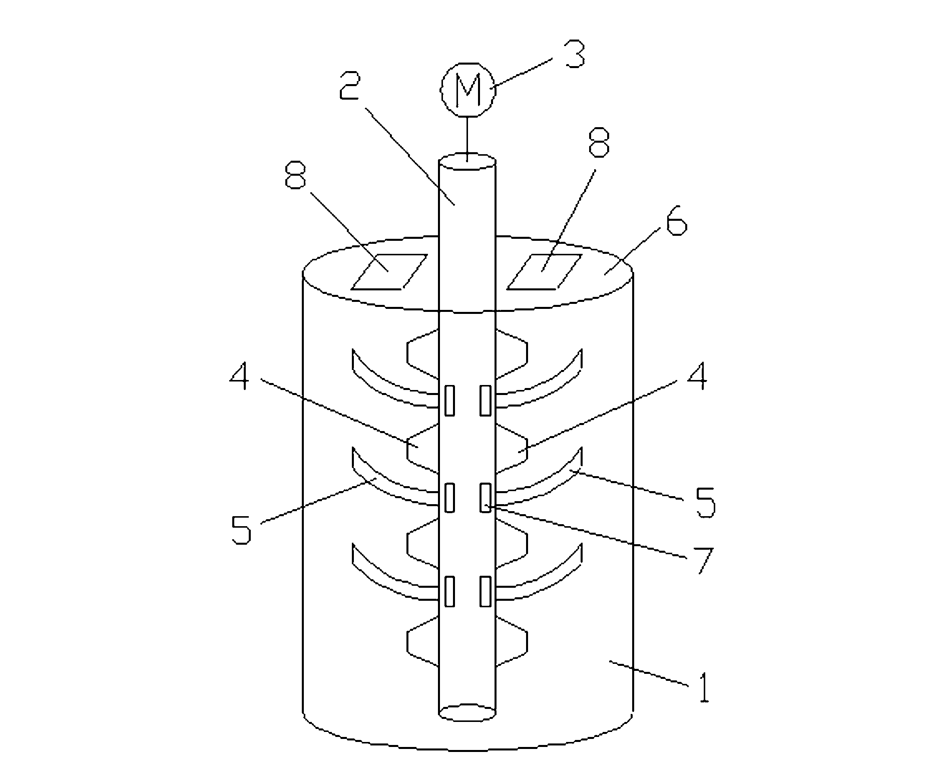
[0016] like figure 1 As shown, a stirring mechanism includes a housing 1 with an open upper end, a stirring shaft 2 disposed in the housing 1, and a motor 3 connected to the stirring shaft 2. The preferred housing 1 of the present invention is cylindrical, which is convenient for the stirring shaft. 2, the stirring shaft 2 is provided with multiple rows of raised groups, the preferred raised groups of the present invention are four rows, and each row of raised groups includes at least two raised groups, and the present invention preferably includes four raised raised groups in each row. four protrusions 4, four protrusions are evenly spaced o...


PUM


Abstract

The invention relates to a mixing mechanism which comprises a shell with an opening in the upper end, a mixing shaft arranged in the shell, and a motor connected with the mixing shaft, wherein a plurality of rows of bulge groups are arranged on the mixing shaft, each row of bulge group comprises at least two bulges, and a mixing blade group is detachably connected to the mixing shaft between every two adjacent bulge groups and comprises two reversely-arranged mixing blades. The mixing mechanism is simple in structure and convenient to use; through arranging the plurality of rows of bulges groups and the mixing blade groups, materials in the shell are uniformly and thoroughly mixed; the mixing blade groups can be dismantled from the mixing shaft so as to be conveniently replaced, thus the cost is saved, and good social and economic benefits are obtained.

Description

technical field [0001] The invention relates to a stirring mechanism. Background technique [0002] Stirrer is a device that makes liquid and gas medium forced convection and uniform mixing. In the existing stirring structure, the stirring shaft is driven by the motor to rotate to complete the stirring of the material. However, the outer surface of this stirring shaft is smooth, and the friction with the material to be stirred is small, resulting in insufficient stirring force at the center of the stirring container, resulting in incomplete and uneven stirring of the material, and low stirring efficiency; and when the stirring blade is stirring When there is damage in the process, it is necessary to replace all the stirring shafts with stirring blades, which will cause energy waste and increase the production cost of the enterprise. Contents of the invention [0003] The invention overcomes the shortcomings of the prior art and provides a stirring mechanism with simp...

Claims


Application Information

Patent Timeline
Patent Type & Authority Applications(China)
IPC IPC(8): B01F7/18B01F3/04
Inventor 范祥荣
Owner 广州金霖塑胶制品有限公司
Why Eureka
Try Eureka