Automatic card cutting device

A cutting device and card technology, applied in metal processing and other directions, can solve problems such as difficulties

Active Publication Date: 2013-09-11
UCHIDA YOKO LTD +2
View PDF7 Cites 5 Cited by
  • Summary
  • Abstract
  • Description
  • Claims
  • Application Information

AI Technical Summary

Problems solved by technology

However, it is difficult to determine the positions of the first head 9A and the second head 9B in the lateral Y direction with high precision.

Method used


Image

  • Automatic card cutting device
  • Automatic card cutting device
  • Automatic card cutting device

Examples


Embodiment Construction

[0020] Preferred embodiments of the present invention will now be described with reference to the accompanying drawings.

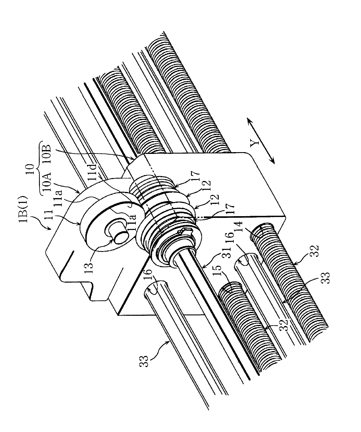
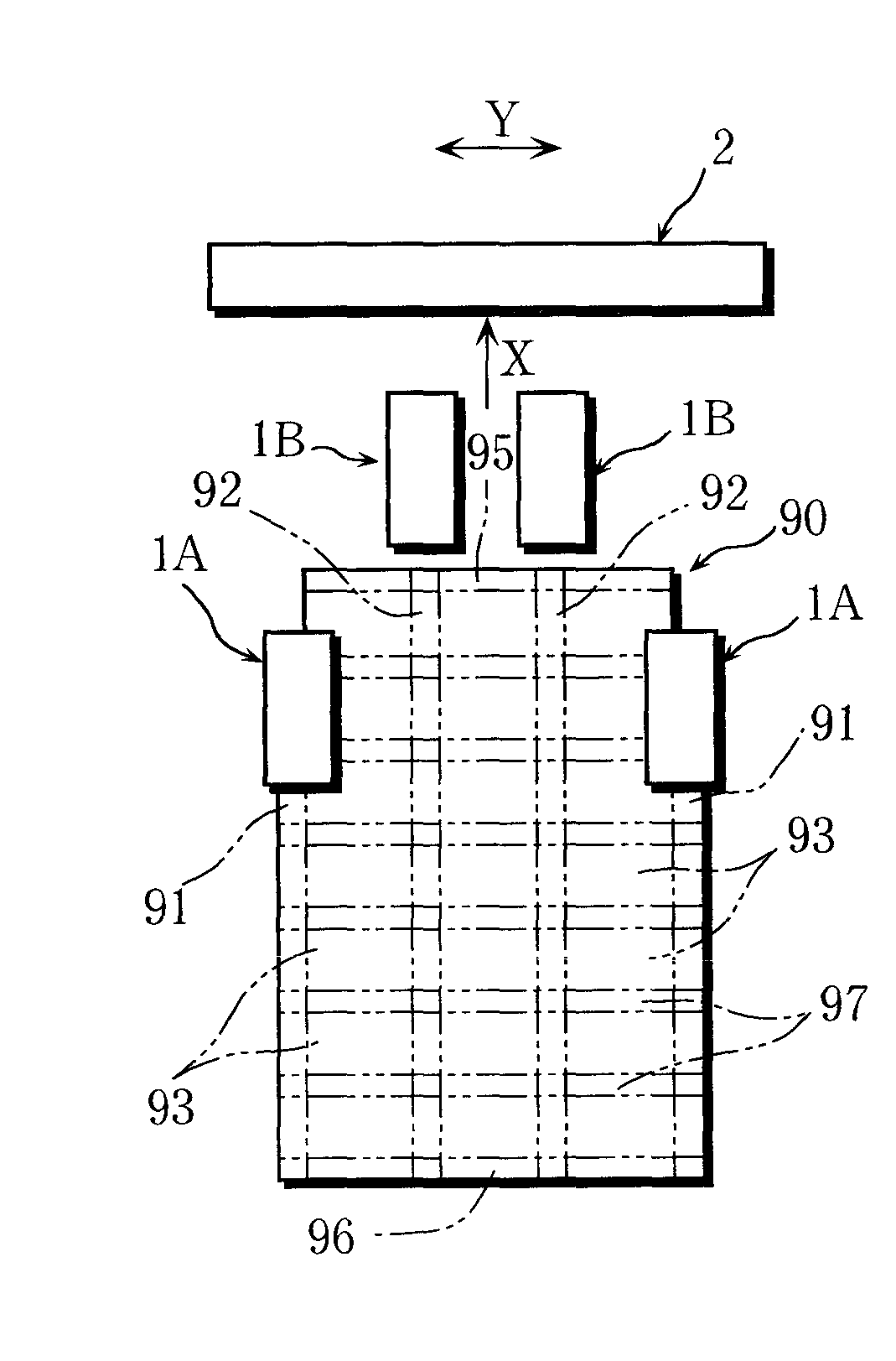
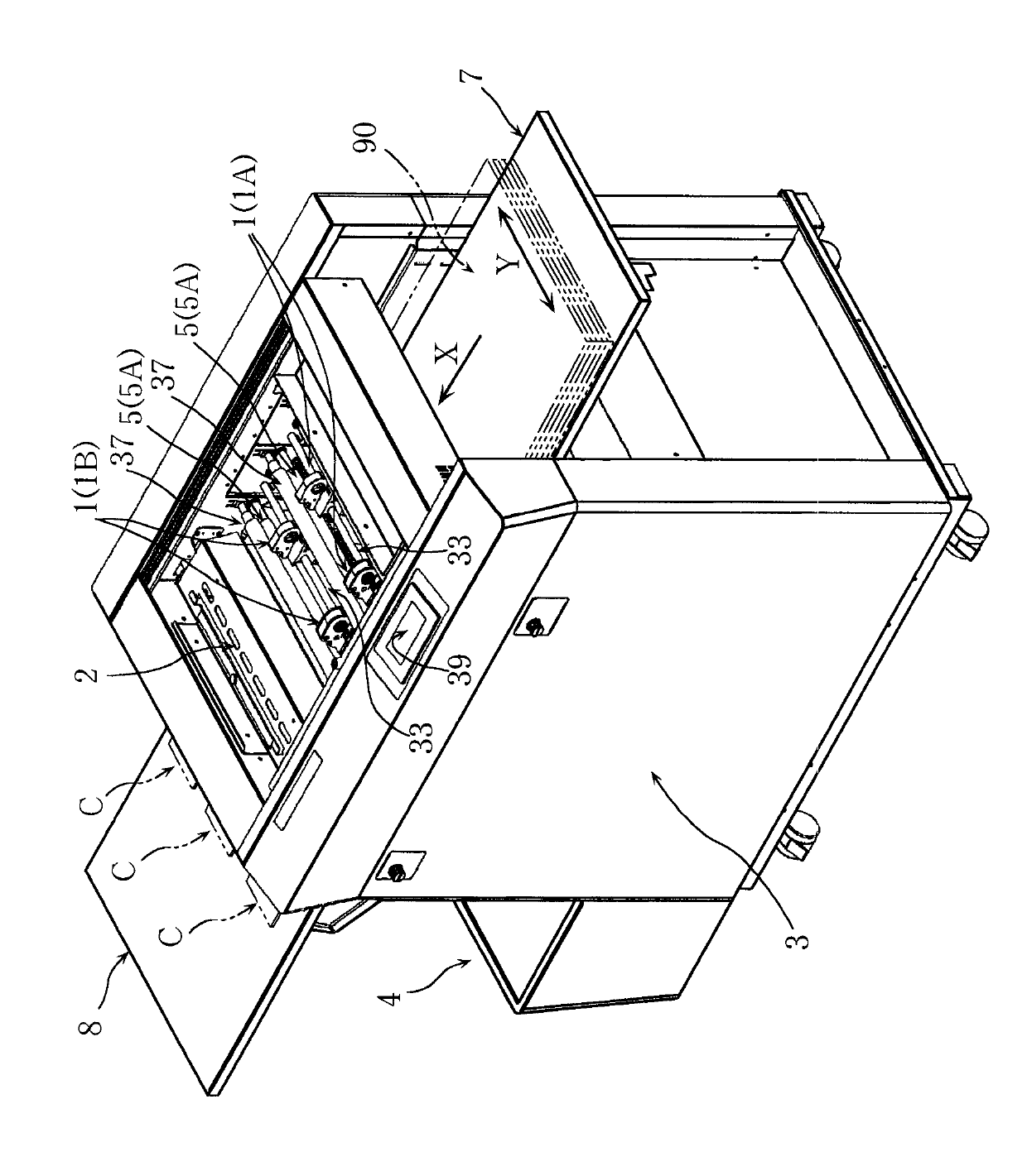
[0021] Regarding the automatic card cutting device of the present invention, the main body frame 3 is provided with: a feed table 7, figure 1 The sheets 90 indicated by double-dashed lines are stacked and placed thereon; a plurality of conveying rollers 5 to contact the underside of the sheets 90 and convey the sheets 90 one by one; a plurality of pressing rollers 37 contacting the upper surfaces of the sheets 90, to prevent the paper 90 from floating; a plurality of shear heads 1 to cut the paper 90 in the conveying direction X; and a discharge table 8 on which the cards C formed by cutting the paper 90 and indicated by a two-dot chain line are deposited . Also, a dust box 4 opened upward is provided outside the main body frame 3 .

[0022] An example of a cutting plan for paper 90 is taken in the figure 2 shown for ease of interpretation. The sheet...


PUM


Abstract

An automatic card cutting device comprises a plurality of convey rollers (5) for conveying paper (90), a plurality of cutting machine heads (1) for cutting the paper (90) in a conveying direction (X), and a transverse cutting machine part (2) used for cutting the paper (90) in a transverse direction (Y) at a right angle with the conveying direction (X) so as to cut the paper (90) into a plurality of cards (C). Each cutting machine head (1) comprises side heads (1A) and middle heads (1B), wherein the side heads (1A) are arranged in a manner that the positions can be adjusted freely in the transverse direction so as to cut lateral border parts (91) of the paper (90) into a strip shape; and each middle head (1B) is provided with a disc-shaped upper blade (11) and a pair of lower blades (12), each lower blade is contacted with the left border part and the right border part (11d) of the upper blade (11) respectively, and the middle head is arranged in a manner that the position can be adjusted freely in the transverse direction so as to cut a longitudinal middle waste part (92) of the paper (90) into a strip shape.

Description

technical field [0001] The invention relates to an automatic card cutting device. Background technique [0002] A conventional automatic card cutting device is provided with a pair of upper rotary blades and lower rotary blades that cut paper in the conveying direction, and a lateral cutter section that cuts paper in a transverse direction at right angles to the conveying direction (see, for example, Japanese Provisional Publication No. .2011-201646). [0003] For example, in a conventional device, a plurality of shearing heads 9 are provided, each of which is as Figure 9 Shown by the dashed-two dotted line in the middle has a lower blade 99 . [0004] Also, each of the plurality of shearing heads is provided with a first head 9A to cut the outer edges 92a on the left and right sides of the longitudinally intermediate waste portion 92, and a second head 92b to cut The inner edges 92b on the left and right sides of the longitudinal intermediate waste portion 92 thereby rem...

Claims


Application Information

Patent Timeline
Patent Type & Authority Applications(China)
IPC IPC(8): B26D1/24B26D7/06B26D7/18
Inventor 远藤寿将高田友树门野一也
Owner UCHIDA YOKO LTD
Why Eureka
Try Eureka