Oil displacement composition, multi-component thermal fluid oil displacement composition containing same, and displacement method

A multi-component thermal fluid and composition technology, which is applied in the direction of drilling composition, production fluid, chemical instruments and methods, etc., can solve the problem of being unable to become an effective replacement technology for Type II and Type III heavy oil, and cannot be effectively transferred to steam flooding and other problems, to achieve the effects of low production cost, suppression of steam overburden phenomenon, and increase of displacement pressure

Active Publication Date: 2015-09-09
PETROCHINA CO LTD
View PDF5 Cites 0 Cited by
  • Summary
  • Abstract
  • Description
  • Claims
  • Application Information

AI Technical Summary

Problems solved by technology

However, in the development of more than 800 million tons of Type II and Type III heavy oil reservoirs in China, there are still problems that cannot be effectively transferred to steam flooding, steam-assisted gravity drainage (SAGD) and burning oil layers after steam injection.
However, the traditional multi-component thermal fluid flooding technology and the measures to improve the effect of steam huff and puff cannot become an effective replacement technology after steam injection in Type II and Type III heavy oil reservoirs in my country.

Method used


Image

  • Oil displacement composition, multi-component thermal fluid oil displacement composition containing same, and displacement method
  • Oil displacement composition, multi-component thermal fluid oil displacement composition containing same, and displacement method
  • Oil displacement composition, multi-component thermal fluid oil displacement composition containing same, and displacement method

Examples


Embodiment 1

[0028] This embodiment provides an oil displacement composition, which includes 15 tons of ammonium bicarbonate, 5 tons of GFPJ-10 high temperature foam agent, 1 ton of high temperature oil displacement agent and 35 tons of water, wherein, the high temperature oil displacement agent is petroleum ring A mixture formed by mixing alkanoic acid diethanolamide and sodium carbonate at a mass ratio of 1:3. The preparation method of the oil-displacing composition comprises the following steps: adding 40°C hot water into ammonium bicarbonate, stirring evenly, adding high-temperature foaming agent and high-temperature oil-displacing agent, and then stirring evenly, that is, the preparation of the present embodiment Oil displacement composition.

[0029] This embodiment also provides a multi-element thermal fluid displacement method, which includes the following steps:

[0030] The above-mentioned oil displacement composition just prepared was transported to Well Du 813-45-91 in Liaohe ...

Embodiment 2

[0036] This example provides a comparison experiment of conventional steam flooding and the multi-element thermal fluid flooding composition of the present invention in a two-dimensional physical simulation model.

[0037] In this flooding experiment, a two-dimensional physical simulation model of 50cm×50cm×4cm was used, and quartz sands of different meshes were loaded into it. The thickness and permeability of the oil layer are consistent with the actual oil layer in Block Jin 45, but the influence of interlayers is ignored. That is to say, only 4 oil layers are filled in the longitudinal direction of the oil layer, the thicknesses are 4.4cm, 7.1cm, 6.5cm, 5.7cm; the permeability is 1.4μm 2 , 2.8 μm 2 , 1.3 μm 2 , 1.7 μm 2 ; The porosity is 22.8%, 26.7%, 23.4%, 24.1%; the rhythm is similar to the actual oil layer; the high permeability layer is located in the upper part of the production layer; the simulated reservoir pressure is 4.0MPa, and the simulated reservoir tempera...

Embodiment 3

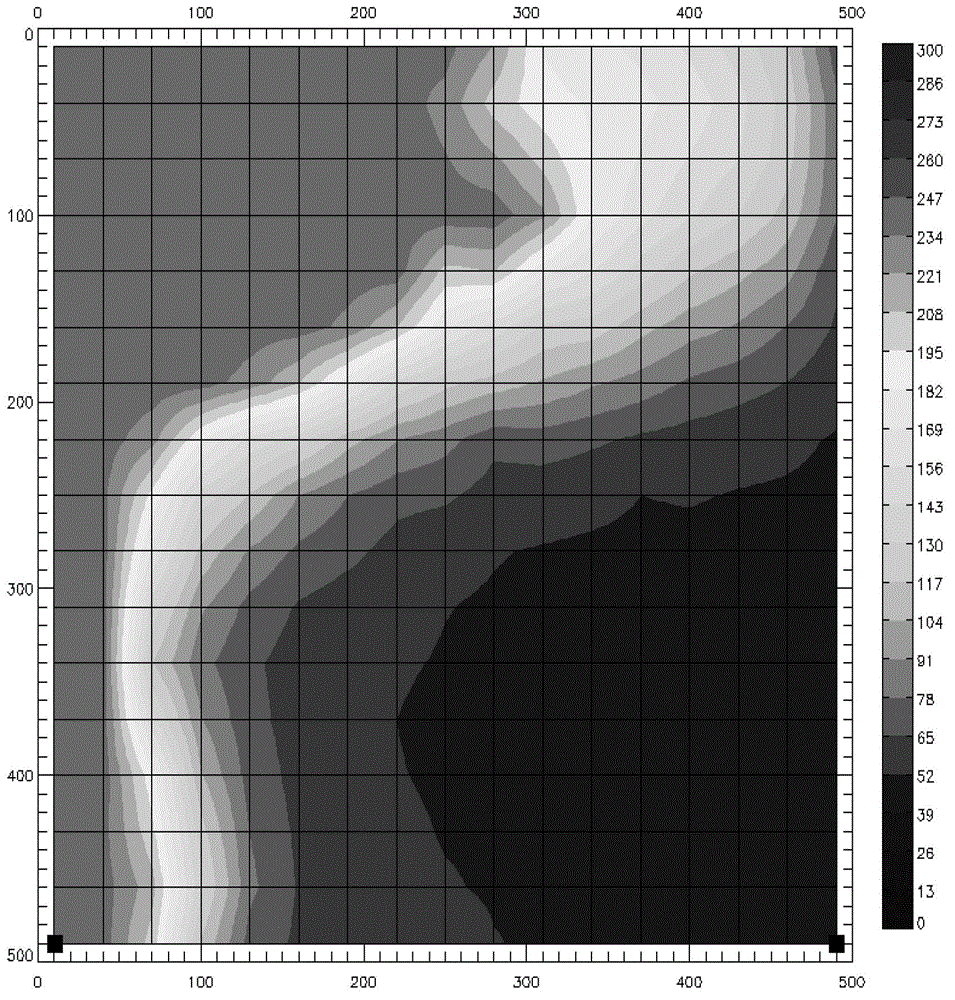
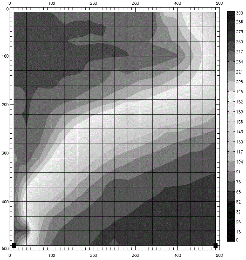
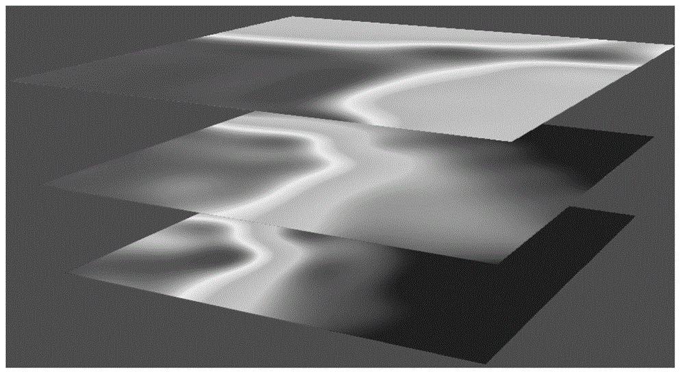
[0059] This example provides a comparison experiment of conventional steam flooding and the multi-component thermal fluid flooding composition of the present invention in a high-temperature and high-pressure steam injection three-dimensional physical simulation experimental device.

[0060] In this displacement experiment, a high-temperature and high-pressure steam injection three-dimensional physical simulation experiment device with an injection-production well spacing of 57cm×40cm was used, and quartz sands of different meshes were placed in it to form thicknesses of 2.5cm, 0.8cm, and 1.5cm. Heterogeneous reservoirs of 466mD, 170mD, and 322mD respectively, with an average reservoir porosity of 38% and an average initial oil saturation of 0.85; a 1 / 4 inverse nine-point area well pattern was selected, and a total of Set up 3 vertical production wells and 1 vertical well injection well; the lower 2 / 3 of the oil layer section of the injection well is shot, and the oil layer sect...


PUM

PropertyMeasurementUnit
thicknessaaaaaaaaaa
thicknessaaaaaaaaaa
porosityaaaaaaaaaa

Abstract

The invention provides an oil displacement composition, a multi-element thermal fluid oil displacement composition containing the same and a displacement method. The oil displacement composition comprises the following components in percentage by weight: 10-45% of ammonium hydrogen carbonate, 0.3-10% of high-temperature foaming agent, 0.2-5% of high-temperature oil displacement agent and the balance of water. The multi-element thermal fluid oil displacement composition provided by the invention comprises the oil displacement composition and water vapor, wherein the mass ratio of the oil displacement composition to the water vapor is 1:(20-100). The multi-element thermal fluid displacement method provided by the invention comprises the following step of: injecting the multi-element thermal fluid oil displacement composition into a heavy oil reservoir through an injection well in an injection-production well group. The multi-element thermal fluid oil displacement composition provided by the invention has low preparation cost and lower energy consumption; a replacing technology after vapor injection into the heavy oil reservoir is formed by combining the displacement technology; and the replacing technology has synergistic effects such as displacement control, quick supplement of stratum energy, improvement of underground seepage capability of fluid and the like so as to improve the crude oil recovery rate.

Description

technical field [0001] The present invention relates to an oil displacement composition, a multi-component thermal fluid displacement composition containing the same and a displacement method, in particular to an oil displacement composition suitable for heavy oil reservoirs, and a multi-component thermal fluid displacement composition containing the same A substance and a displacement method belong to the technical field of petroleum exploitation. Background technique [0002] Heavy oil resources are widely distributed in my country, but there are many types of heavy oil reservoirs and complex geological conditions. Type II and III heavy oils have the characteristics of deep oil burial, high viscosity, thin oil layers, low permeability, and active edge and bottom water. The thermal efficiency of steam is low and the control pressure is high, so it is difficult to effectively develop the existing technology. In order to efficiently develop these heavy oil reservoirs, oilfiel...

Claims


Application Information

Patent Timeline
Patent Type & Authority Patents(China)
IPC IPC(8): C09K8/58C09K8/592E21B43/24
Inventor 沈德煌王红庄蒋有伟张运军席长丰李秀峦王伯军李晓玲罗建华韩静
Owner PETROCHINA CO LTD
Why Eureka
Try Eureka