Rotary gas valve control mechanism

A control mechanism and rotary technology, which is applied in engine control, mechanical equipment, machine/engine, etc., can solve problems such as complex control systems, and achieve the effect of reasonable design and simple structure

Active Publication Date: 2013-09-11
SHANGHAI JIAO TONG UNIV
View PDF9 Cites 33 Cited by
  • Summary
  • Abstract
  • Description
  • Claims
  • Application Information

AI Technical Summary

Problems solved by technology

[0003] After searching the existing technical literature, it is found that Chinese patent number ZL200410063439.5, patent name: electronic exhaust gas recirculation gas control device, this patent technology provides a device for controlling the exhaust gas recircu

Method used


Image

  • Rotary gas valve control mechanism
  • Rotary gas valve control mechanism
  • Rotary gas valve control mechanism

Examples


Embodiment

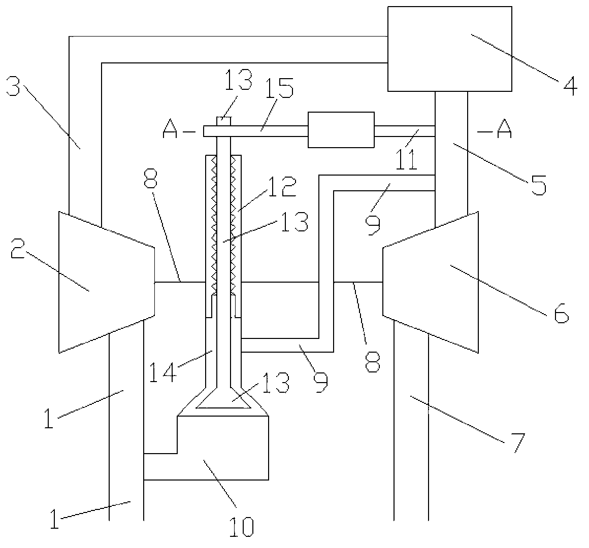
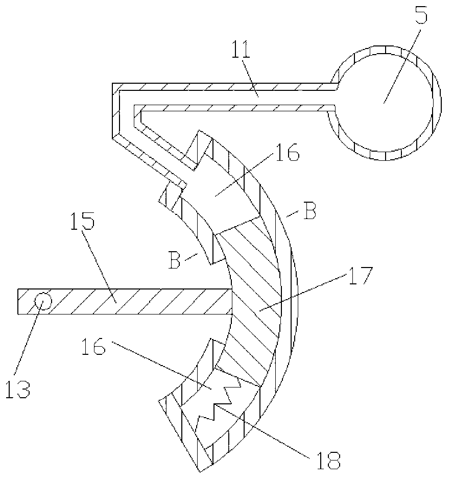
[0015] Such as Figure 1 to Figure 3 Shown, the present invention comprises compressor intake pipe 1, compressor 2, engine intake pipe 3, engine 4, engine exhaust pipe 5, turbine 6, turbine exhaust pipe 7, connecting shaft 8, first connecting pipe 9, the first Two connecting pipes 10, a third connecting pipe 11, a valve seat 12, a valve body 13, a rotating shaft 15, a volume cavity 16, a rotating body 17 and an elastic member 18, the air inlet and outlet of the compressor 2 are respectively connected with the outlet of the air inlet pipe 1 of the compressor. Air port, the air inlet of engine intake pipe 3 are connected, and the air inlet and outlet of engine 4 are connected with the air outlet of engine intake pipe 3, the air inlet of engine exhaust pipe 5 respectively, and the air inlet and outlet of turbine 6 are connected with engine exhaust respectively. The air outlet of the pipe 5 and the inlet of the turbine exhaust pipe 7 are connected, the compressor 2 and the turbine...


PUM


Abstract

The invention discloses a rotary gas valve control mechanism and belongs to the technical field of mechanical design. The rotary gas valve control mechanism comprises a gas compressor, an engine, a turbine, connecting pipes, a valve seat, a valve body, a rotary shaft, an accommodating cavity, a rotator and an elastic component, wherein the rotator is mounted in the accommodating cavity and is in sealed contact with the inner wall face of the accommodating cavity, the lower wall face of the rotator is connected with the lower wall face of the accommodating cavity through the elastic component, two ends of a first connecting pipe are communicated with gas inlets of an engine exhaust pipe and an accommodating chamber respectively, and two ends of a third connecting pipe are communicated with the engine exhaust pipe and the upper wall face of the accommodating cavity. When the engine exhaust pipe is high in pressure, the rotator drives the valve body to rotate clockwise, exhaust gas recirculation rate of the engine is large, and the engine is low in explosion pressure; and when the engine exhaust pipe is low in pressure, the rotator drives the valve body to rotate anticlockwise, the exhaust gas recirculation rate of the engine is small, and oil consumption of the engine is low. The rotary gas valve control mechanism is reasonable in design, simple in structure and applicable to an exhaust gas recirculation system of the supercharged engine.

Description

technical field [0001] The invention relates to an exhaust gas recirculation system in the technical field of mechanical design, in particular to a rotary valve control mechanism. Background technique [0002] Harmful emissions from engines are a major source of air pollution. With the increasing importance of environmental protection, the goal of reducing harmful emissions from engines has become an important direction for engine development in the world today. With the world's consumption of petroleum products increasing year by year, international oil prices remain high, and the economy of diesel vehicles is becoming more and more prominent, which makes diesel engines occupy an increasingly important position in vehicle power. Therefore, it is the primary task of diesel engine designers to carry out research on the control methods of harmful emissions from diesel engines. Exhaust gas recirculation system is to send a small part of the exhaust gas produced by the diesel e...

Claims


Application Information

Patent Timeline
IPC IPC(8): F02D21/08
Inventor 李忠照叶兵胡振王梓恒
Owner SHANGHAI JIAO TONG UNIV
Why Eureka
Try Eureka