Vibration type point load tester

A point load and tester technology, applied in the direction of testing material strength by applying repetitive force/pulsation force, testing material strength by applying stable tension/compression, etc., can solve the problem that the strength or failure performance cannot be given, and the sample is not considered Mechanical properties and other issues, to achieve the effect of light and easy to carry the instrument, and improve the speed of testing

Active Publication Date: 2013-09-11
CENT SOUTH UNIV
View PDF6 Cites 6 Cited by
  • Summary
  • Abstract
  • Description
  • Claims
  • Application Information

AI Technical Summary

Problems solved by technology

The existing point load instruments basically stay at the level of measuring the point load strength of the specimen under static load and pressure, without considering the mechanical properties of the specimen under vibration or impact load
However, in the current mechanized excavation construction of high-stress rock mass, high ground stress and vibration load act at the same time, and the traditional point load instrument cannot give the strength or failure performance under this combined load state.
[0004] It can be seen that there is currently no experimental instrument that can test the failure performance of irregular rock blocks under the combined action of static load and vibration load.

Method used


Image

  • Vibration type point load tester
  • Vibration type point load tester
  • Vibration type point load tester

Examples


Embodiment 1

[0028] Embodiment 1. Utilize the device to study the point load strength of rock under static load

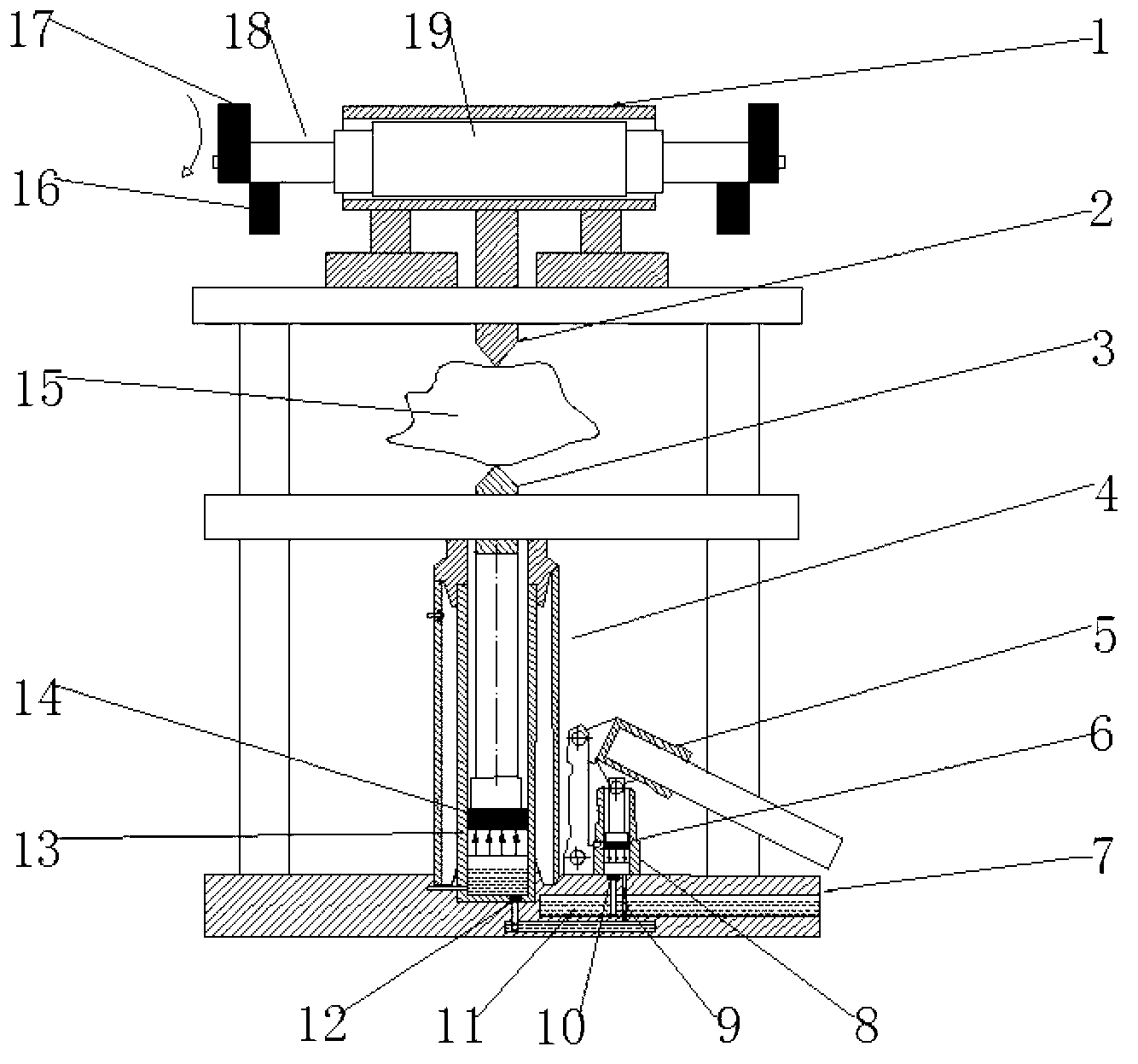
[0029] (1) Select one of the first group of specimens, take the direction of the minimum size of the specimen as the loading direction, place the specimen between the upper and lower pressure cones, and adjust the static pressure device to raise the lower pressure cone, and finally The upper and lower pressure cones are in close contact with the upper and lower surfaces of the irregular block.

[0030] (2) Record the distance D between the vertices of the upper and lower pressure cones, with an error of no more than ±2%; record the minimum specimen width W perpendicular to the loading direction, with an error of no more than ±5%; if the sides are not parallel to each other, Then W presses (W 1 +W 2 ) / 2 calculation.

[0031] (3) Increase the load steadily so that the specimen fails within 10 to 60 seconds. Record the reading F of the oil pressure gauge when the specimen is d...

Embodiment 2

[0046] Embodiment 2. Using the device to study the influence of different exciting forces on the rock point load strength

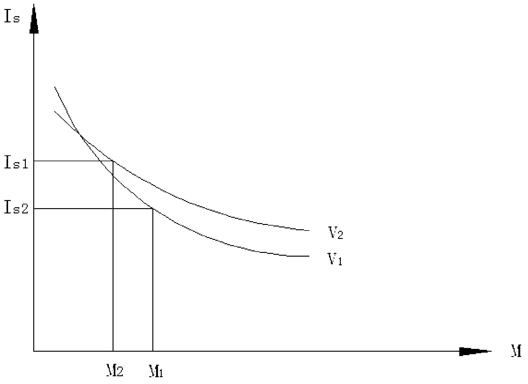
[0047] Take one test piece from the second set of test pieces. After installing the test piece, turn on the vibration motor, keep the vibration frequency unchanged, and choose an exciting force M 1 , apply the static load at the same loading rate as the static load test until the specimen fails. Follow the same steps to keep the vibration frequency ν 1 unchanged, changing the excitation force (M 2 , M 3 ...), to test other specimens.

[0048] During the experiment, in addition to recording the parameters F, W, and D of the specimen required for the above-mentioned static load experiment, it is also necessary to record the speed n of the vibration motor (for calculating the vibration frequency ν) and the exciting force M. See Appendix 2 for the experimental data recording form. The calculation method of the point load strength of the specimen is simi...

Embodiment 3

[0050] Embodiment 3. Using the device to study the influence of different vibration frequencies on the rock point load strength

[0051] Take one test piece from the third set of test pieces. After installing the test piece, turn on the vibration motor, keep the exciting force constant, and select a vibration frequency ν 1 , apply the static load at the same loading rate as the static load test until the specimen fails. Follow the same steps, keep the exciting force constant, change the vibration frequency (ν 2 、ν 3 ...) to complete the tests on other specimens.

[0052] During the experiment, in addition to recording the parameters F, W, and D of the specimen, it is also necessary to record the excitation force and speed n of the vibration motor (used to calculate the vibration frequency ν). See Appendix 3 for the experimental data recording form. The calculation method of the point load strength of the specimen is the same as in Example 2.

[0053] If the data in Appen...


PUM


Abstract

The invention discloses a vibration type point load tester. The vibration type point load tester is formed by a static loading unit and a vibration loading unit, wherein the static loading unit is formed by mounting a static pressurizing device (4) on a bottom platform of a bracket (7); the vibration loading unit is characterized in that a vibration motor (1) is mounted on an upper platform of the bracket (7); an upper pressurizing cone (2) which is vertically arranged and the bottom of the vibration motor (1) are connected to form a whole body; a lower pressurizing cone (3) is connected with an upper pressurizing piston of the static pressurizing device (4) and can move up and down through a central hole of a separation plate; the upper pressurizing cone (2) and the lower pressurizing cone (3) are located on the same axial central line; a rock test piece (15) is placed between the upper pressurizing cone (2) and the lower pressurizing cone (3). The vibration type point load tester disclosed by the invention inherits the advantage that a conventional point load tester is light and easy to carry; meanwhile, the capability of applying a vibration load is further increased. The vibration type point load tester can be conveniently carried to a construction site to test the strength of movable and static point loads of the test piece. The invention provides the unique vibration type point load tester for rock mechanics researches.

Description

technical field [0001] The invention relates to an experimental device for measuring the point load strength of rock, especially capable of measuring the point load failure characteristics of rock under vibration load. technical background [0002] In the construction of deep rock mass engineering, we found that the combined rock breaking effect of dynamic load and static load is better than that of static load, especially in the mechanical excavation of jointed rock mass under high stress control by using roadheader The vibration load is applied on the rock-breaking foundation by pressing and cutting, and the tunneling efficiency is greatly improved. The tunneling efficiency is closely related to the static stress and the vibration load. Therefore, in the field construction, it is necessary to quickly and accurately provide the optimal vibration load under different ground stress conditions. Due to the irregular shape of engineering rocks and the development of joints and ...

Claims


Application Information

Patent Timeline
Patent Type & Authority Applications(China)
IPC IPC(8): G01N3/12G01N3/38
Inventor 周子龙吴志波李夕兵董陇军马春德
Owner CENT SOUTH UNIV
Why Eureka
Try Eureka