
Special high-voltage testing device for transformers

A special device and transformer technology, applied in the field of high-voltage special devices for transformer testing, can solve the problems of the truck itself being easy to collide with objects, affecting the progress of the test process, and inconsistent wiring methods, so as to prevent mechanical damage, protect safety, and ensure safety. Effect

Inactive Publication Date: 2013-09-11
STATE GRID CORP OF CHINA +2
View PDF8 Cites 3 Cited by
  • Summary
  • Abstract
  • Description
  • Claims
  • Application Information

AI Technical Summary

Problems solved by technology

Since there are many test items for these transformers, and the wiring methods are not uniform, and the test wiring is changed repeatedly, it is necessary for the test personnel to operate the bucket truck and climb the transformer body many times, which will cause a series of problems.
Firstly, climbing the transformer, operating the trolley and changing the wiring requires a lot of time and manpower, which seriously affects the progress of the test process; secondly, climbing the transformer and working on the transformer itself have high safety risks, and moving the working position many times is likely to cause damage. Personal injury; in addition, the location of the large-scale transformer bushing is relatively high, and the cooperation of the bucket truck is required when testing the wiring. Frequent bucket truck operations also have unsafe factors such as high-altitude operations, the safety of the bucket truck itself, and objects that are easy to collide.

Method used


Image

  • Special high-voltage testing device for transformers
  • Special high-voltage testing device for transformers
  • Special high-voltage testing device for transformers

Examples


Embodiment Construction

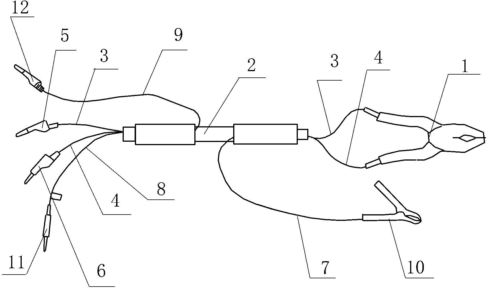
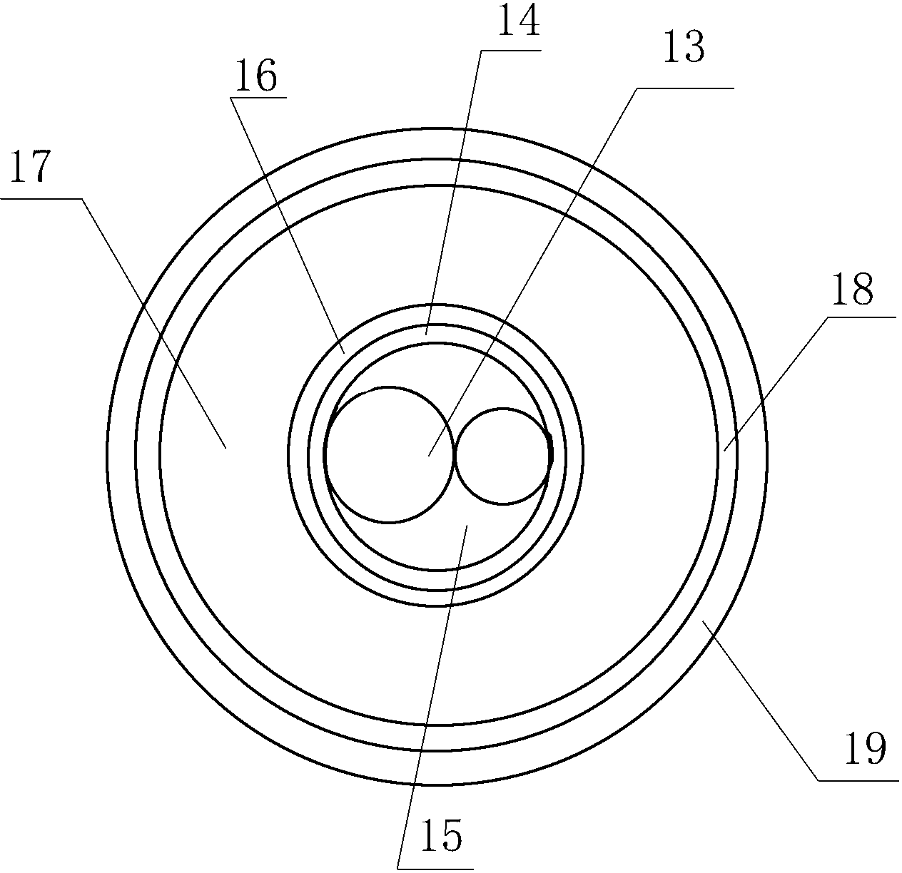
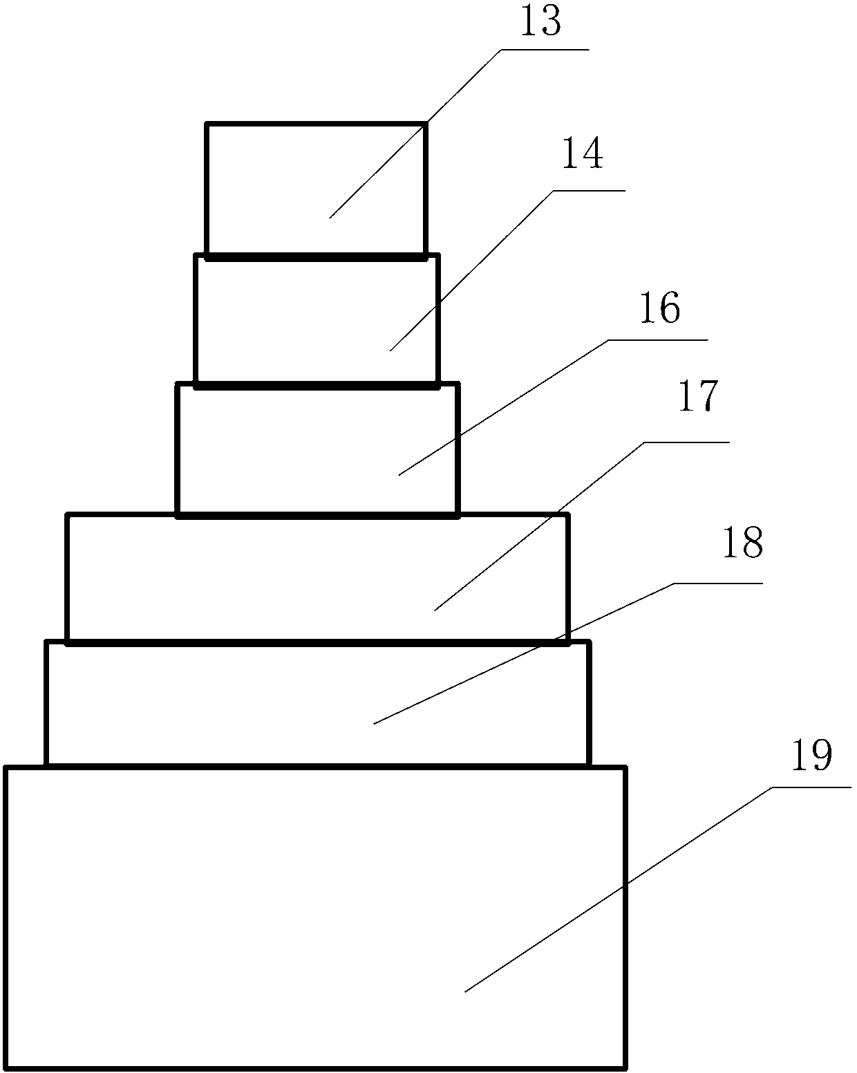
[0010] exist figure 1 , figure 2 with image 3 Among them, the present invention provides a special device for transformer test high voltage, which includes wiring clamp 1, test high voltage lead bushing 2, voltage line 3 and current line 4, and the two terminals of wiring clamp 1 are connected with voltage line 3 and current line respectively. Line 4, voltage line 3 and current line 4 extend into the test high-voltage lead bushing 2 and are respectively connected with a voltage line plug 5 and a current line plug 6. In the test high-voltage lead bushing 2, an upper shielding line 7 and a lower shielding line are also provided. Wire 8 and outer shielding wire 9, one end of voltage wire 3 and current wire 4 is connected with upper shielding wire 7, one end of upper shielding wire 7 is connected with voltage wire 3 and current wire 4, and the other end of upper shielding wire 7 is connected with The terminal clamp 10 is connected with the lower shielded wire 8 and the outer s...


PUM


Abstract

The invention provides a special high-voltage testing device for transformers. The special high-voltage testing device is characterized in that two wiring terminals of wiring pliers (1) of the special high-voltage testing device are respectively connected with a voltage line (3) and a current line (4), the voltage line (3) and the current line (4) extend into a high-voltage lead testing bushing (2) and then are respectively connected with a voltage line plug (5) and a current line plug (6), an upper shielded line (7) is connected to one end of the voltage line (3) and one end of the current line (4), one end of the upper shielded line (7) is connected with the voltage line (3) and the current line (4), a wiring clip (10) is connected to the other end of the upper shielded line (7), a lower shielded line (8) and an outer shielded line (9) are respectively connected to the other end of the voltage line (3) and the other end of the current line (4), the lower shielded line (8) and the outer shielded line (9) are respectively connected with the voltage line (3) and the current line (4), and a lower shielded line plug (11) and an outer shielded line plug (12) are respectively connected to the other end of the lower shielded line (8) and the other end of the outer shielded line (9).

Description

technical field [0001] The invention relates to a high-voltage special device for transformer testing. Background technique [0002] The main transformer plays an important role in the power system, so the test of the main transformer is particularly important. During the routine test of the current main transformer, a series of test items need to be completed, including measuring short-circuit impedance, DC resistance, insulation and dielectric loss, etc. Since there are many test items for these transformers, and the wiring methods are not uniform, and the test wiring is changed repeatedly, it is necessary for the test personnel to operate the bucket truck and climb the transformer body many times, which causes a series of problems. Firstly, climbing the transformer, operating the trolley and changing the wiring requires a lot of time and manpower, which seriously affects the progress of the test process; secondly, climbing the transformer and working on the transformer i...

Claims


Application Information

Patent Timeline
IPC IPC(8): G01R31/00G01R1/04G01R1/06
Inventor 孙志何菲
Owner STATE GRID CORP OF CHINA
Learn More