Microgravity test verification method for accumulator performance in a plate-type propellant management device

A plate-type propellant and management device technology, applied in the field of microgravity test, can solve the problems that cannot be obtained from foreign literature, no mention of test system design, leaky test system, etc., to facilitate the analysis of test results and fluid management And the effect of good liquid storage performance and reasonable test method

Active Publication Date: 2015-10-21
BEIJING INST OF CONTROL ENG
View PDF5 Cites 0 Cited by
  • Summary
  • Abstract
  • Description
  • Claims
  • Application Information

AI Technical Summary

Problems solved by technology

[0003] At the same time, since the development of plate-type PMD propellant storage tanks and related test verification technologies involve national security, countries that have mastered this technology often impose technical blockades. The information that can be provided by foreign countries is not comprehensive and can only serve as a reference. None of the related articles mentions the detailed test system design. For the mechanism research of plate-type PMD components, it is necessary to build a test system by itself, carry out a large number of microgravity tests, summarize the verification methods of microgravity tests, and obtain sufficient first-hand information. Basic information is impossible to obtain from foreign literature
[0004] In summary, a microgravity test verification method for the performance of a plate-type PMD-accumulator is the result of exploration and summary during the development of a large-capacity plate-type PMD propellant storage tank. The entire test method is brand new. There are no relevant literature and materials to learn from, and foreign countries rarely disclose similar test systems

Method used


Image

  • Microgravity test verification method for accumulator performance in a plate-type propellant management device
  • Microgravity test verification method for accumulator performance in a plate-type propellant management device
  • Microgravity test verification method for accumulator performance in a plate-type propellant management device

Examples


Embodiment Construction

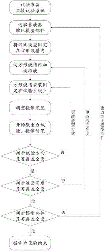
[0029] Specific embodiments of the present invention will be further described in detail below in conjunction with the accompanying drawings.

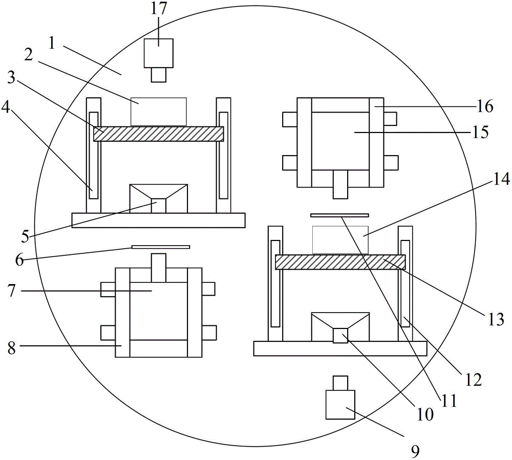
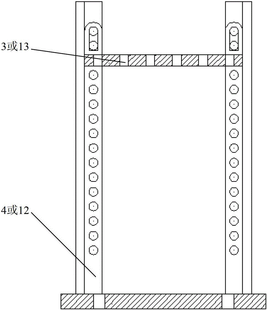
[0030] Such as figure 1 As shown, the test system adopted by the method of the present invention includes parts such as test system substrate 1, height-adjustable test bracket assembly, image acquisition system, and lighting system, and the parts such as height-adjustable test bracket assembly, image acquisition system, and lighting system are all Two sets are symmetrically arranged on the test system base plate 1, and the test system has the ability to conduct microgravity tests of two test models at the same time.

[0031] The test system substrate 1 is a light circular aluminum plate with a wood honeycomb layer inside, which is used to realize the compact installation and fixing of the height-adjustable test bracket components, image acquisition system, lighting system, etc., and realize the test system and microgravity at the same ...


PUM


Abstract

Provided is a method for verifying a performance microgravity test of a hydraulic accumulator in a plate-type propellant management device. The scale model components of hydraulic accumulators of different types are used as test objects, the microgravity test implementation method of the scale model components of different hydraulic accumulators of various types and the changing strategies of different conditions of a microgravity test are mainly designed in the test method, and test preparations, test procedures, a simulated liquid level height selecting strategy and the like are stipulated. The test method is reasonable in design, strong in operability and capable of achieving all the microgravity tests of the scale model components of the hydraulic accumulators, video recording is carried out on the whole process of accumulating liquid, and follow-up test result analysis and hydraulic accumulator optimization design are facilitated. According to the test method, the flow liquid management property and the liquid accumulating capacity of the model of the hydraulic accumulator can be obtained, and the performance of the hydraulic accumulator is verified.

Description

technical field [0001] The invention relates to a microgravity test verification method for the performance of a liquid accumulator, which is a part of a plate-type propellant management device (PDM). Microgravity tests of various accumulator scale models. Background technique [0002] With the rapid development of large-scale truss platform satellites in the world, propellant tanks using plate PMDs have become the mainstream in the world. Since the end of the "Eleventh Five-Year Plan", the development of large-capacity plate-type PMD propellant storage tanks has been carried out. The plate-type PMD prototype has been developed, and the ground demonstration test of the plate-type PMD fluid transmission performance and management performance has been carried out. This demonstration test can only verify the local performance of the plate-type PMD, and cannot truly reflect its ability to manage, control and transmit fluids using surface tension in a space environment. Therefo...

Claims


Application Information

Patent Timeline
Patent Type & Authority Patents(China)
IPC IPC(8): G01V7/16G01V7/04
Inventor 李永胡齐潘海林陈健魏延明李泽
Owner BEIJING INST OF CONTROL ENG
Why Eureka
Try Eureka