
Optical scanning device and image forming device using the optical scanning device

An optical scanning device and sub-scanning technology, which is applied in the field of optical scanning device and image forming device, can solve problems such as difficult mold processing, and achieve the effect of easy mold processing and excellent optical performance

Active Publication Date: 2015-09-09
KYOCERA DOCUMENT SOLUTIONS INC
View PDF3 Cites 0 Cited by
  • Summary
  • Abstract
  • Description
  • Claims
  • Application Information

AI Technical Summary

Problems solved by technology

Therefore, mold processing is accompanied by greater difficulties

Method used


Image

  • Optical scanning device and image forming device using the optical scanning device
  • Optical scanning device and image forming device using the optical scanning device
  • Optical scanning device and image forming device using the optical scanning device

Examples


Embodiment Construction

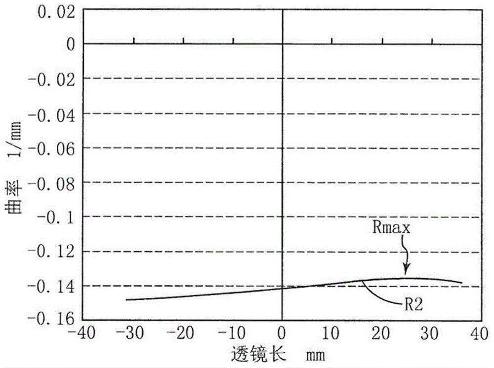
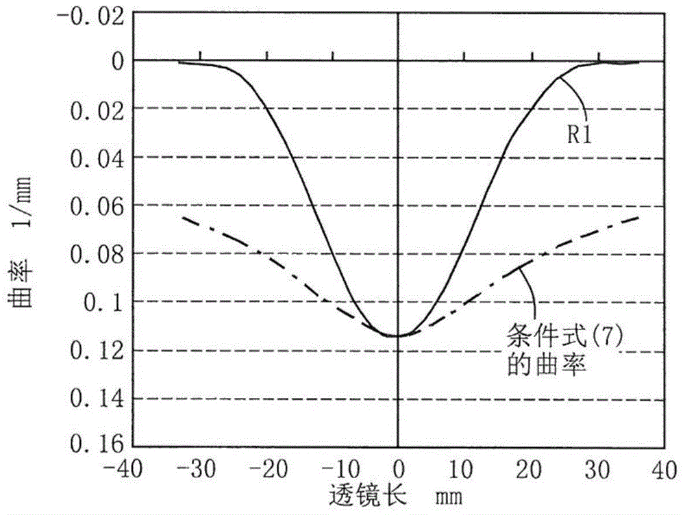
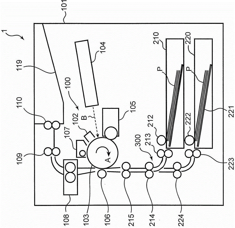
[0023] Next, an optical scanning device according to an embodiment of the present invention will be described with reference to the drawings. figure 1 It is a cross-sectional view showing a schematic configuration of a printer 1 (an example of an image forming apparatus) according to an embodiment of the present invention. In addition, the image forming apparatus is not limited to the printer 1, and may be a copier, a facsimile, a multifunction machine, or the like. The printer 1 includes a box-shaped housing 101 , an image forming unit 100 accommodated in the housing, an optical scanning device 104 , and supply cassettes 210 and 220 . The supply cassettes 210 and 220 are detachably attached to the lower portion of the printer 1 .

[0024] The image forming unit 100 performs processing of forming a toner image on a sheet, and includes a charging device 102 , a photosensitive drum 103 (image carrier), a developing device 105 , a transfer roller 106 , a cleaning device 107 , an...


PUM


Abstract

An optical scanning device includes a light source, a deflector, an incident optical system and one scanning lens. The scanning lens includes a first face and a second face. In a main scanning direction cross section of the scanning lens, when a scanning range is separated, with on axis as a reference, into an image height region of a first direction and an image height region of a second direction that is opposite to the first direction, the incident optical system is disposed on a side of the image height region of the first direction. Curvature of the first face in a sub scanning direction cross section decreases from on axis toward off axis in the main scanning direction, and curvature of the second face in the sub scanning direction cross section increases from off axis of the first direction toward the second direction in the main scanning direction.

Description

technical field [0001] The present invention relates to an optical scanning device including a scanning lens for forming an image of deflected and scanned light on a surface to be scanned, and an image forming device using the optical scanning device. Background technique [0002] For example, the general optical scanning device used in laser printers, copiers, etc. includes: a light source that emits laser light; a polygon mirror that reflects the laser light and deflects and scans the laser light; A scanning lens that forms an image on the peripheral surface (scanned surface). As the scanning lens, a lens having a distortion aberration (fθ characteristic) in which an angle of incident light is proportional to an image height is used. In addition, the scan lens is generally manufactured by mold molding using a resin material. [0003] One of the optical characteristics required in such an optical scanning device is that the curvature of field is well corrected and that th...

Claims


Application Information

Patent Timeline
Patent Type & Authority Patents(China)
IPC IPC(8): G02B26/12G03G15/04
CPCG02B13/0005B41J2/473G02B26/10G02B26/101G02B26/125G03G15/04036
Inventor 吉田真悟冈村秀树中野一成
Owner KYOCERA DOCUMENT SOLUTIONS INC
Learn More