A variable saucer-shaped airship UAV
What is Al technical title?
Al technical title is built by PatSnap Al team. It summarizes the technical point description of the patent document.
An unmanned aerial vehicle, dish-shaped technology, applied in the field of unmanned aerial vehicles, can solve the problems of poor portability, short airborne time, prolonged airborne time, etc., and achieve the effects of reducing power usage, reducing operating noise, and extending battery life.
Active Publication Date: 2021-06-01
WUHAN UNIV OF TECH
View PDF10 Cites 0 Cited by
Summary
Abstract
Description
Claims
Application Information
AI Technical Summary
This helps you quickly interpret patents by identifying the three key elements:
Problems solved by technology
Method used
Benefits of technology
Problems solved by technology
However, the existing unmanned aerial vehicles generally have the following problems: (1) the short time in the air, the existing solution is to develop new fuel cells, aluminum batteries, etc. to increase the air time of the aircraft, but the increased battery life through this method The time is limited and the cost is high. If a foldable micro-airship is used, since the airbag itself has buoyancy in the air, it can hover without the high-speed movement of the blades. All the power is used to propel the airship forward, and the time spent in the air is greatly extended.
(2) The problem of electromagnetic interference crash, strong wind disturbance crash, (3) the problem of poor portability, the existing solution is to use the method of reducing the volume of the airbag, but this will greatly reduce the payload of the airship and make the function of the airship restricted
Method used
Image
Click on the blue label to locate the original text in one second.
Reading with bidirectional positioning of images and text.
Examples
Embodiment Construction
[0017] The technical solutions in the present invention will be clearly and completely described below in conjunction with the accompanying drawings and embodiments.
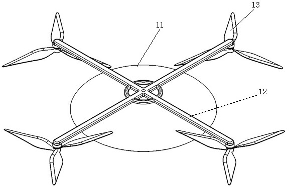
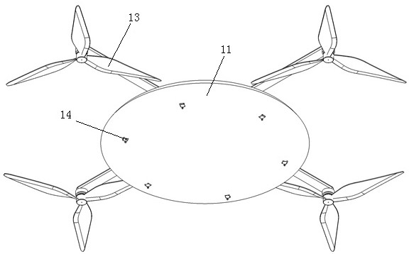
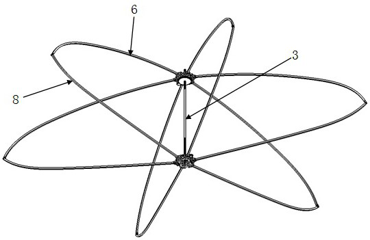
[0018] like Figures 1 to 6 As shown, the present embodiment provides a variable saucer-shaped airship drone, including a saucer-shaped airbag 11, a motor arm 12, an airbag bracket assembly, a compound eye camera 14, and a propeller 13. The inside of the saucer-shaped airbag is composed of an airbag bracket assembly Support, the airbag bracket assembly includes a bearing seat 1, a large gear 2, a screw 3, a motor 4, a pinion 5, an upper support rod 6, a lower support rod 8, a connecting rod 7, a disc 9, and a support rod fixing seat 10, The disc 9 is divided into upper and lower layers, which are identical, the upper support rod 6 and the lower support rod 8 are connected by a connecting rod 7, and the other end of the upper support rod 6 is hingedly connected with the support rod fixing seat 10 , the upper and...
PUM
Abstract
The invention belongs to the technical field of unmanned aerial vehicles and provides a variable disc-shaped airship unmanned aerial vehicle, including a disc-shaped airbag, a motor arm, an airbag bracket assembly, a compound eye camera, and a propeller. The inside of the disc-shaped airbag is supported by the airbag bracket assembly , the airbag bracket assembly includes a bearing seat, a large gear, a screw, a motor, a pinion, an upper support rod, a lower support rod, a connecting rod, a disk, and a support rod fixing seat, and a motor is fixed on the disk, and the motor drives The small gear meshes with the large gear, and then through the meshing of the thread in the center of the bearing seat and the screw rod, the bearing seat moves up and down along the screw rod, and then the disc drives the upper support rod to swing. The disc on the top of the airbag bracket and the four motors The arms are connected, and the end of each motor arm is provided with a motor seat, and the output shaft of the motor is connected with the propeller, and 6 compound eye cameras are installed symmetrically on the lower part of the disc-shaped airbag. The device of the invention has the advantages of simple structure, convenient use and portability, and can effectively improve the endurance time of the drone.
Description
technical field [0001] The invention belongs to the technical field of unmanned aerial vehicles, and in particular relates to a variable saucer-shaped airship unmanned aerial vehicle. Background technique [0002] At present, unmanned aerial vehicles have been widely used in military reconnaissance and detection, missile early warning, aerial photography, security monitoring, search and rescue in disaster areas and other fields. However, the existing unmanned aerial vehicles generally have the following problems: (1) The problem of short time in the air, the existing solution is to develop new fuel cells, aluminum batteries, etc. The time is limited and the cost is high. If a foldable micro-airship is used, since the airbag itself has buoyancy in the air, it can hover without the high-speed movement of the blades. All the power is used to propel the airship forward, and the airborne time is greatly extended. (2) The problems of electromagnetic interference crashes and stron...
Claims
Application Information
Patent Timeline
Application Date:The date an application was filed.
Publication Date:The date a patent or application was officially published.
First Publication Date:The earliest publication date of a patent with the same application number.
Issue Date:Publication date of the patent grant document.
PCT Entry Date:The Entry date of PCT National Phase.
Estimated Expiry Date:The statutory expiry date of a patent right according to the Patent Law, and it is the longest term of protection that the patent right can achieve without the termination of the patent right due to other reasons(Term extension factor has been taken into account ).
Invalid Date:Actual expiry date is based on effective date or publication date of legal transaction data of invalid patent.