

Reticulated shell-annular truss frame-irregular-shaped combination column combined support spherical tank system capable of slightly moving
A technology of annular truss and combined columns, applied in the field of storage tanks for oil storage, can solve the problems of poor seismic performance of spherical storage tanks, and achieve the effects of reasonable stress, good wind resistance and strong adaptability
- Summary
- Abstract
- Description
- Claims
- Application Information
AI Technical Summary
Problems solved by technology
Method used
Image

Examples
Embodiment Construction
[0048] Below in conjunction with accompanying drawing, the present invention will be further described:
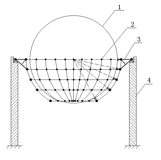
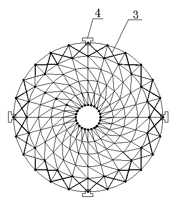
[0049] combine figure 1 , figure 2 As shown, this kind of reticulated shell-ring truss-special-shaped composite column joint support and micro-movable spherical tank system includes composite spherical tank 1, reticulated shell-ring truss-special-shaped composite column joint support, rubber ball-damper for shock absorption and energy dissipation Device; joint support of reticulated shell-ring truss-special-shaped composite column, ring truss 3 surrounds reticulated shell 2, ring truss 3 is connected with special-shaped composite column 4; composite spherical tank 1 is set on the joint of reticulated shell-ring truss-special-shaped composite column For support, a rubber ball-damper shock-absorbing and energy-dissipating device is arranged between the reticulated shell node 18 and the composite spherical tank 1. The annular truss 3 is arranged between the reticulated she...
PUM
 Abstract
Description
Claims
Application Information