A magnetic suspension bearing

A magnetic levitation bearing and magnetic pole technology, applied in the direction of bearings, shafts and bearings, mechanical equipment, etc., can solve problems affecting normal use, equipment overheating damage, rotor overheating, etc., to reduce eddy current loss, heat generation, and work efficiency Improvement, simple structure and easy-to-use effect

Active Publication Date: 2015-12-02
HEFEI SMARTER TECH GROUP CORP
View PDF7 Cites 0 Cited by
  • Summary
  • Abstract
  • Description
  • Claims
  • Application Information

AI Technical Summary

Problems solved by technology

The current magnetic suspension bearings are still in use today. figure 1 As shown, that is, the inner wall of the stator is evenly distributed with a plurality of armature structures wound with coils along its circumference, so that the electromagnetic adsorption of the rotor is realized by relying on the structure of multiple sets of N and S poles arranged around the rotor along the radial direction of the rotor. Suspension effect, although the above-mentioned structure has the magnetic levitation function based on the rotor, its defects cannot be underestimated. The main reasons are: on the one hand, every time the rotor rotates once, each area of ​​the rotor will inevitably move frequently. After such figure 1 Each group of N and S poles shown ( figure 1 The dotted line in the middle is a schematic diagram of the flow path of the magnetic force line), and the corresponding induction area on it will also be transformed into a magnetic pole, that is, the charging and discharging operation will be carried out continuously, so as to ensure the adsorption of each pair of N and S poles to the rotor. However, the rotor It must be constantly rotating during work, and the above-mentioned rotor areas continue to pass through each set of N and S poles, resulting in frequent charging and discharging, which inevitably causes eddy current loss and causes electric heating effects, eventually leading to overheating of the rotor Phenomenon, light affects its normal use effect, and causes overheating damage to the equipment; on the other hand, the formation of N and S poles are both composed of armatures and coils. The armature of the traditional structure may be integrally formed with the stator. The coil is wound as a whole, and once the bearing is processed, it cannot be changed. If it is necessary to increase the suspension force in special occasions, it can only be done by replacing the bearing. The replacement is cumbersome and costly, or it is necessary to make the armature in advance. And after the coil is wound, it is fixed on the inner wall of the rotor. This method not only prevents the top of each armature from forming an accurate circumferential surface due to various installation errors, but also causes the phenomenon of non-concentricity between the outer wall of the rotor and the inner wall of the stator, resulting in two Those who can't adapt to the pole work normally at all, which brings great troubles to the actual operators

Method used


Image

  • A magnetic suspension bearing
  • A magnetic suspension bearing
  • A magnetic suspension bearing

Examples


Embodiment Construction

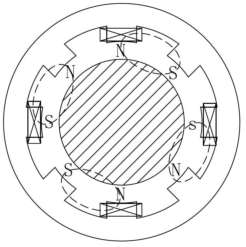
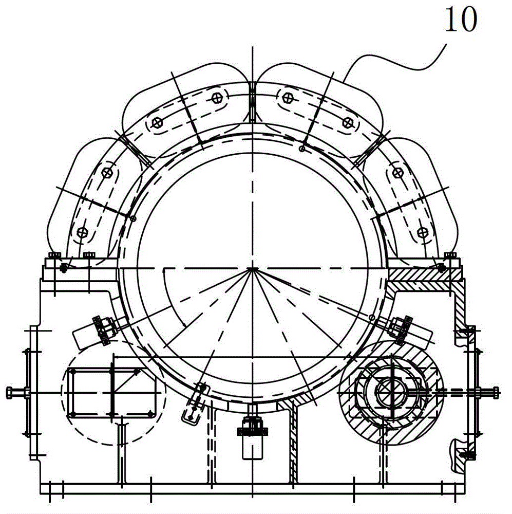
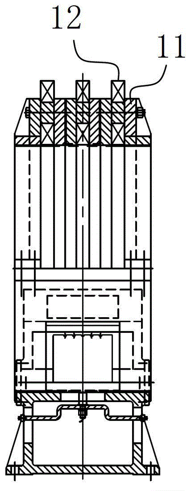
[0012] A magnetic suspension bearing, including a rotor and a stator assembly adapted to it, forming a suspension cooperation relationship between the two; the stator assembly includes a magnetic pole unit 10 on it for forming the rotor suspension power, and the magnetic pole unit 10 The arrangement direction of the N and S poles is set in the same direction as the axial length direction of the stator assembly.

[0013] The actual structure of the present invention is as Figure 2-6 As shown, by abandoning the traditional placement method of arranging the N and S poles of the magnetic pole unit 10 along the radial direction of the stator assembly, it breaks through the abnormal arrangement structure in which the N and S poles are arranged in the same direction as the axial length of the stator assembly , thereby ingeniously playing the unique effect of avoiding the frequent conversion of magnetic poles when the rotor is working; in actual operation, on the one hand, due to the...


PUM


Abstract

The invention discloses a magnetic suspension bearing which comprises a rotor and a stator component matched with the rotor, and suspended cooperation relationship is formed between the rotor and the stator component. The stator component comprises a magnetic pole unit which is arranged on the stator component and is used for forming rotor suspension power; the arrangement directions of the N pole and the S pole of the magnetic pole unit are the same as that of the axial length of a stator. The magnetic suspension bearing eliminates a traditional way of arranging the N pole and the S pole of the magnetic pole unit along the radial direction of the stator, and adopts the arrangement structure of enabling the directions of the N pole and the S pole to be the same as that of the axial length of the stator component, so that the unique effect of preventing the magnetic poles from being frequently converted in the working process of the rotor can be ingeniously achieved.

Description

technical field [0001] The invention belongs to the field of mechanical magnetic suspension, and in particular relates to a magnetic suspension bearing. Background technique [0002] Magnetic bearing (Magnetic Bearing) is a device structure that uses magnetic force to suspend the rotor in the air, so that there is no mechanical contact between the rotor and the stator. Compared with traditional ball bearings, sliding bearings and oil film bearings, magnetic bearings have no mechanical contact, and the rotor can run to a high speed, with small mechanical wear, low energy consumption, low noise, long life, no lubrication, no oil Pollution and other advantages, especially suitable for high-speed, vacuum, ultra-clean and other special environments. The current magnetic suspension bearings are still in use today. figure 1 As shown, that is, the inner wall of the stator is evenly distributed with a plurality of armature structures wound with coils along its circumference, so tha...

Claims


Application Information

Patent Timeline
Patent Type & Authority Patents(China)
IPC IPC(8): F16C32/04
CPCF16C32/0461
Inventor 岳光明蔚伟储彬金克锦黄世伟陈飞
Owner HEFEI SMARTER TECH GROUP CORP
Why Eureka
Try Eureka