Device and method for measuring dynamic stiffness frequency-dependent characteristics of return springs

A technology of heddle spring and measuring device, which is applied in the direction of measuring device, vibration test, machine/structural component testing, etc., can solve problems such as only considering static stiffness and static elongation, and neglecting dynamic characteristics of heddle spring.

Active Publication Date: 2013-09-18
WUJIANG WANGONG ELECTROMECHANICAL EQUIP
View PDF7 Cites 6 Cited by
  • Summary
  • Abstract
  • Description
  • Claims
  • Application Information

AI Technical Summary

Problems solved by technology

In the past, only the static stiffness and static elongation were considered when designing th

Method used


Image

  • Device and method for measuring dynamic stiffness frequency-dependent characteristics of return springs
  • Device and method for measuring dynamic stiffness frequency-dependent characteristics of return springs
  • Device and method for measuring dynamic stiffness frequency-dependent characteristics of return springs

Examples


Embodiment 1

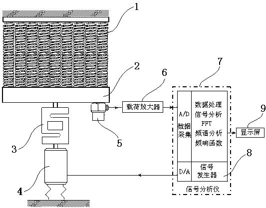
[0046] see figure 1 , 2 As shown, a measuring device and method for the first few longitudinal natural frequencies of the heald spring, including a measuring device and method for the first few longitudinal natural frequencies of the heald spring and a measuring device and method for the frequency characteristics of the dynamic stiffness of the heald spring.

[0047] see figure 1As shown, the measuring device for the first few orders of longitudinal natural frequencies of the heald spring includes a heald spring group 1, a force sensor 3, an exciter 4, an acceleration sensor 5 and a signal analyzer 7, and the heald spring group 1 is It consists of 9 springs side by side, and the weight of the spring bottom plate 2 is 16 kg; the upper end of the heddle spring group 1 is fixedly grounded, and the lower end is affixed to the spring bottom plate 2, and the spring bottom plate 2 passes the force The sensor 3 is connected with the exciter 4, the other end of the exciter 4 is fixed...

Embodiment 2

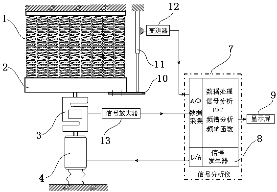
[0064] see figure 1 , 3 As shown, a measuring device and method for the first few longitudinal natural frequencies of the heald spring, including a measuring device and method for the first few longitudinal natural frequencies of the heald spring and a measuring device and method for the frequency characteristics of the dynamic stiffness of the heald spring.

[0065] see figure 1 As shown, the measuring device for the first few orders of longitudinal natural frequencies of the heald spring includes a heald spring group 1, a force sensor 3, an exciter 4, an acceleration sensor 5 and a signal analyzer 7, and the heald spring group 1 is It consists of 9 springs side by side, and the weight of the spring bottom plate 2 is 16 kg; the upper end of the heddle spring group 1 is fixedly grounded, and the lower end is affixed to the spring bottom plate 2, and the spring bottom plate 2 passes the force The sensor 3 is connected with the exciter 4, the other end of the exciter 4 is fixe...


PUM


Abstract

The invention discloses a device and a method for measuring dynamic stiffness frequency-dependent characteristics of return springs. The device comprises a return spring set, a force sensor, a signal analyzer, an acceleration sensor and a displacement sensor. The upper end of the return spring set is fixedly grounded. The lower end of the return spring set is fixedly connected to a spring base plate. The spring base plate is connected with an exciter or a six-connecting rod mechanism through the force sensor to drive the return spring to vibrate or reciprocate. The acceleration sensor or the displacement sensor is disposed on the spring base plate. The return spring set vibrates or reciprocates to allow the acceleration sensor or the displacement sensor to output response signals to the signal analyzer, and the signal analyzer acquires dynamic stiffness frequency-dependent characteristics of the return springs through data processing and FFT (fast Fourier transform) analysis. By researching the dynamic stiffness of the return springs, the highest operation speed of a passive shedding mechanism can be explored, and basis is provided for improvement of the passive shedding mechanism.

Description

[0001] technical field [0002] The invention belongs to the field of air-jet looms, and in particular relates to a measuring device and method for frequency-varying characteristics of dynamic stiffness of a heald spring. [0003] Background technique [0004] The shedding system is the part with the highest failure rate of the loom. There are various dynamic performance problems in the shedding system. The reason is that the dynamic parameters of the shedding system have changed with the increase of operating speed and the passage of time; the second is that the system The stiffness of the heald spring is related to the operating frequency. As the speed of the loom increases, the first few resonance frequencies of the heald spring overlap with the operating frequency of the shedding system. Especially in the resonance area, the dynamic stiffness of the heald spring becomes very small, resulting in the shedding system The quality of operation is degraded and failures conti...

Claims


Application Information

Patent Timeline
IPC IPC(8): G01M7/02
Inventor 周平祝章琛
Owner WUJIANG WANGONG ELECTROMECHANICAL EQUIP
Why Eureka
Try Eureka