Radar-imaging of a scene in the far-field of a one-or two-dimensional radar array

a radar array and far-field technology, applied in the field of radar imaging of scenes, can solve the problems inability to meet certain requirements of sub-optimal radar aperture lengths, and inability to use optimal aperture length imaging algorithms such as range migration and chirp-scaling algorithms

Inactive Publication Date: 2011-06-16
THE EURO UNION
View PDF12 Cites 91 Cited by
  • Summary
  • Abstract
  • Description
  • Claims
  • Application Information

AI Technical Summary

Benefits of technology

[0004]The present invention provides a method of radar-imaging ...

Problems solved by technology

To date, the interest in radar imaging systems with sub-optimal aperture lengths has been very limited.
In particular, the imaging algorithms used with optimal aperture lengths (typically a few tens of kilometers long in case of space-borne SAR), such as the range migration and chirp-scaling algorithms, do not satisfy certain requirements...

Method used


Image

  • Radar-imaging of a scene in the far-field of a one-or two-dimensional radar array
  • Radar-imaging of a scene in the far-field of a one-or two-dimensional radar array
  • Radar-imaging of a scene in the far-field of a one-or two-dimensional radar array

Examples


examples

A. Numerical Simulations

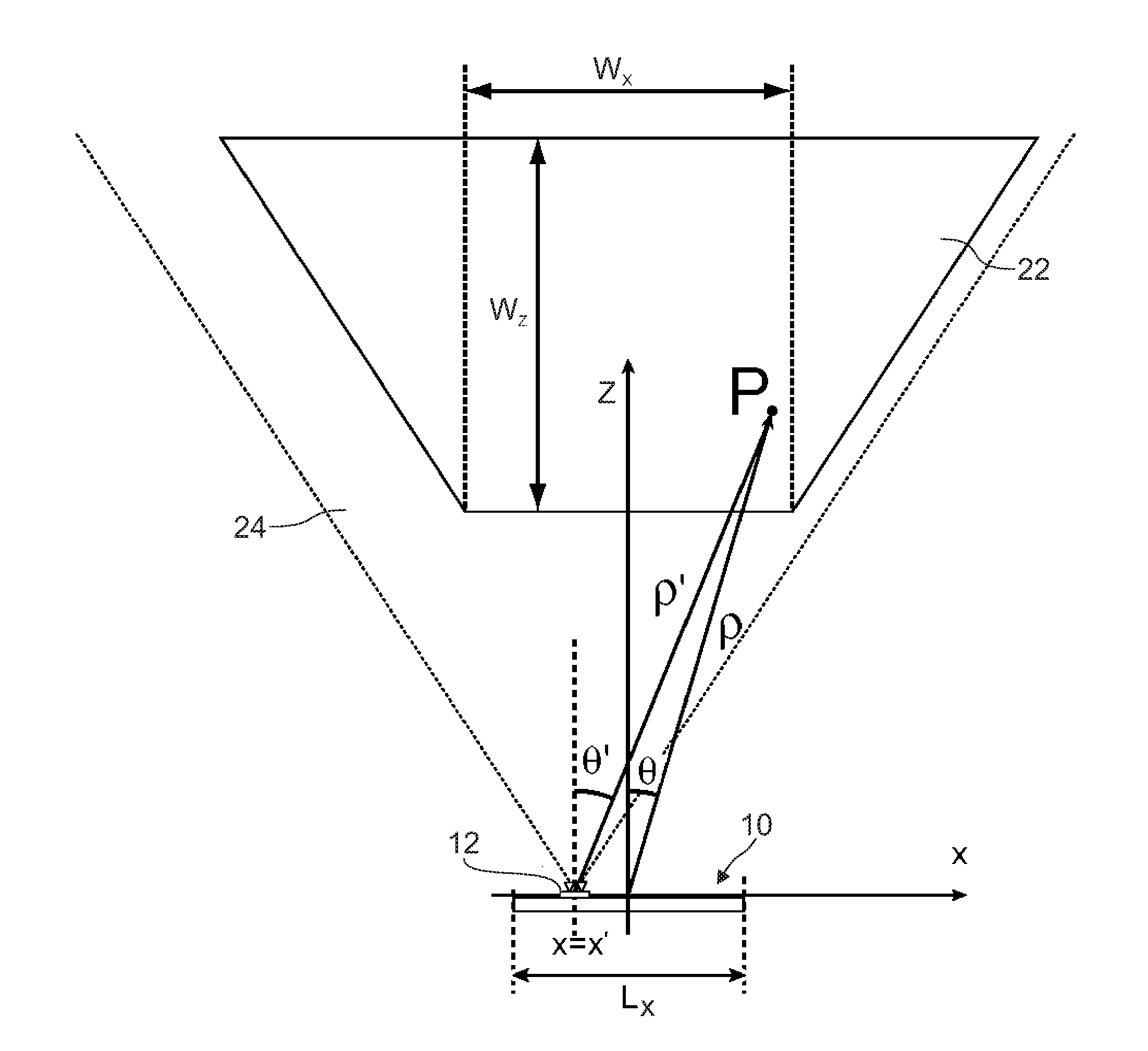
[0066]The FPFA has been validated with a series of numerically simulated scenarios (in the 2D case). As a first example, a scene consisting of 5×5 point scatterers uniformly distributed in range and azimuth, with 500 mx=2 m). The aperture length to range resolution is Lx / δr≈1.3. Prior to the formation of the images, a four-terms Blackman-Harris window was applied both along frequency and the linear coordinate of the radar aperture dimensions. The reflectivity images were computed using the FPFA and, for comparison, the TDBA. In the FPFA, the first four terms of the image series in eq. (27), i.e., Ip(α, β) with 0≦p≦3. The dynamic range of the images was 100 dB. From the results, it clearly followed that the first term of the image series, the zeroth order expansion, is already an excellent approximation of the true reflectivity. In fact, it was found that the second term in the series has reflectivity values, on a pixel by pixel basis, at least 25 dB below tho...


PUM


Abstract

A method of radar-imaging a scene in the far-field of a one-dimensional radar array, comprises providing an array of backscatter data D(fm, x′n) of the scene, these backscatter data being associated to a plurality of positions x′n, n=0 . . . N−1, N>1, that are regularly spaced along an axis of the radar array. The backscatter data for each radar array position x′n are sampled in frequency domain, at different frequencies fm, m=0 . . . M−1, M>1, defined by fm=fc−B/2+m−Δf, where fc represents the center frequency, B the bandwidth and Δf the frequency step of the sampling. A radar reflectivity image 1m′, βn′) is computed in a pseudo-polar coordinate system based upon the formula (2) with formula (3) where j represents the imaginary unit, formula (A) is the baseband frequency, FFT2D denotes the 2D Fast Fourier Transform operator, αm′, m′=0 . . . M−1, and βn′, n′=0 . . . N−1 represent a regular grid in the pseudo-polar coordinate system, and Pmax is chosen >0 depending on a predefined accuracy to be achieved. A corresponding method of radar-imaging a scene in the far-field of a two-dimensional radar array is also proposed.
I(αm,βn)=p=0PmaxIp(αm,βn),Formula(2)I(αm,βn)=1p![-j2πβnfc]pFFT2D[D(fm,xn)(f^m,xn)p],Formula(3)f^m=-B/2+m·ΔfFormula(A)

Description

TECHNICAL FIELD[0001]The present invention generally relates to radar-imaging a scene located in the far-field of a radar aperture, more particularly to a method for converting a radar image from raw radar data.BACKGROUND[0002]The present invention is applicable for image reconstruction from radar data acquired by a synthetic aperture radar (SAR) or by a physical radar array. SAR is a well-known and well-developed technique to produce high-resolution images. A large number of imaging algorithms are operationally used in different civilian and military application domains. A common requirement for such algorithms is that of producing imagery with the highest possible resolution. It is well known that the limits of the resolution in range and cross-range are, respectively, dictated by the frequency bandwidth and the physical dimension of the radar aperture. In practice, a criterion to assess the optimality of a SAR system is to compare the achieved cross-range resolution in the imager...

Claims


Application Information

Patent Timeline
IPC IPC(8): G01S13/89
CPCG01S13/32G01S13/9011G01S13/9023
Inventor FORTUNY-GUASCH, JOAQUIM
Owner THE EURO UNION
Why Eureka
Try Eureka