Detecting and identifying method for annular coding mark point

A recognition method and a technology of marking points, which are applied in character and pattern recognition, instruments, computer components, etc., can solve the problems of high shooting angle and environmental requirements of coding marking points, large influence of shooting angle, poor image recognition effect, etc.

Inactive Publication Date: 2013-09-18
TIANJIN POLYTECHNIC UNIV
View PDF0 Cites 55 Cited by
  • Summary
  • Abstract
  • Description
  • Claims
  • Application Information

AI Technical Summary

Problems solved by technology

The detection and identification of coded markers is one of the difficulties in close-range photogrammetry. At present, the researches in this area at home and abroad mainly include (1) Forbes K proposed the arc segmentation method when using coded markers for calibration in 2002. This method It is easy to cause uneven segmentation, which affects the final decoding result
(2)Thomas Doring et al. applied Forbes K twelve-bit coding markers in scanner calibration, and increased the number of samples sampled by using the coding ring segmentation method, but at the same time it will increase the calculation cost, and this method is affected by the photographic The angle has a great influence; (3) Liang Jin, Liu Jianxin and Hu Hao from Xi'an Jiaotong University applied ring-shaped coding markers to camera calibration, and their decoding method has higher requirements on the shooting angle and environment of the coding markers
(4) Wang Man and Ye Zhenglin used morphological operators for recognition, but this method is greatly affected by the camera angle, and the recognition effect on images with complex backgrounds is poor

Method used


Image

  • Detecting and identifying method for annular coding mark point
  • Detecting and identifying method for annular coding mark point
  • Detecting and identifying method for annular coding mark point

Examples


Embodiment Construction

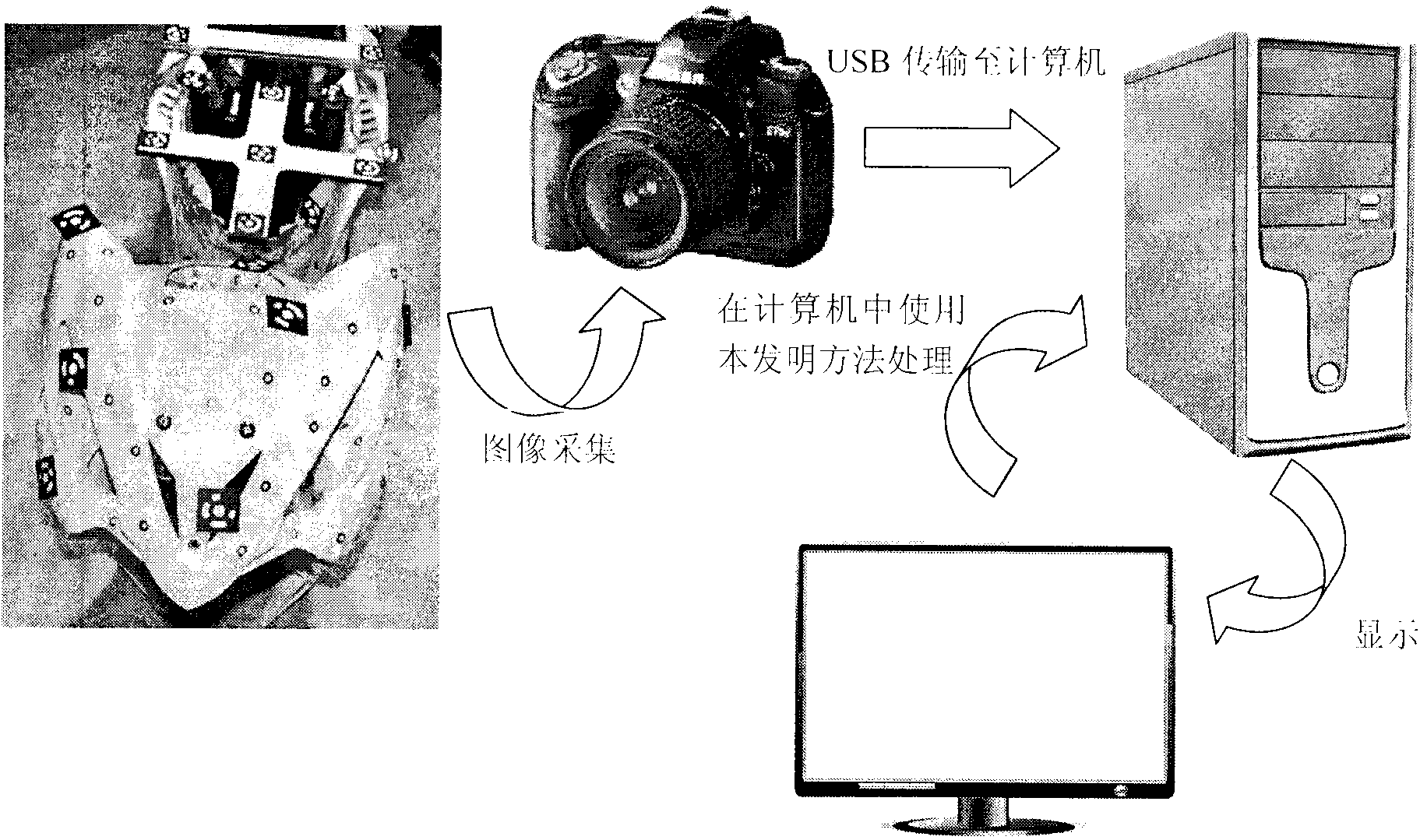
[0042] The system diagram of the present invention is as follows figure 1 As shown, the present invention provides a detection and recognition method for a ring-shaped coding mark point, which can reach the sub-pixel level for the location of the code mark point, and can reduce the angle between the camera optical axis and the normal line of the code mark point to identify the code mark point. The impact of the accuracy rate fully meets the requirements of the positioning accuracy and recognition accuracy of the coded marker points in close-range photogrammetry.

[0043] The hardware system of the detection and recognition system of the described circular coding marking point comprises:

[0044] Large artifacts for pasting coded markers;

[0045] A number of ring-coded marking points for detection and identification;

[0046]A color or black-and-white video camera for capturing images;

[0047] Computer for precision control, image acquisition and data processing.

[0048]...


PUM


Abstract

The invention belongs to the field of close-range photogrammetry and relates to a detecting and identifying method for an annular coding mark point. The method includes that first, canny edge detection is conducted on a collected image, an outline centroid is closed through a series of limiting conditions and calculation, and noise and non-coding mark points are filtered; then least square ellipse fitting is adopted, coding mark point location is conducted, an ellipse fitting error is combined to judge a partition coding mark point outline, and the outline is filled; finally, ALPC transformation for transforming a local concentric ellipse into parallel straight lines is provided, the ALPC transformation is conducted on the partitioned coding mark point, and transformed image characteristics are used for decoding. By means of the detecting and identifying method, location of the coding mark point can reach a sub pixel level, local shape characteristics of a concentric ellipse are transformed into shape characteristics of parallel straight lines which are easy to detect and calculate, coding mark point identifying speed is improved, and effects of an included angle of a camera optical axis and a coding mark point normal on the coding mark point identifying accuracy can be reduced.

Description

technical field [0001] The invention relates to a method for detecting and identifying ring-shaped coding marking points, and more specifically, the invention relates to a method for detecting and identifying ring-shaped coding marking points for full-scale splicing of large workpieces. Background technique [0002] In machine 3D vision measurement, for images collected from large fields of view and from multiple angles, the accuracy of image matching is an important link to improve the accuracy of 3D data stitching. In the process of image matching, it is required to accurately detect and identify the corresponding points of the image. However, for high-resolution large field of view images, it is very difficult to identify the corresponding points of the two images, which requires the use of a marker point with a unique code value, which is artificially pasted on the key feature points of the measured object to take pictures , to identify the feature points of the two ima...

Claims


Application Information

Patent Timeline
Patent Type & Authority Applications(China)
IPC IPC(8): G06K9/46
Inventor 宋丽梅陈昌曼陈卓覃名翠李大鹏唐欢
Owner TIANJIN POLYTECHNIC UNIV
Why Eureka
Try Eureka