
Charger indicating lamp circuit

An indicator light circuit and charger technology, applied in the field of circuits, can solve the problems such as the inability to control the indicator light of the charger to be on or off, and the complexity of the indicator light circuit.

Inactive Publication Date: 2013-09-18
HONG FU JIN PRECISION IND (SHENZHEN) CO LTD +1
View PDF0 Cites 2 Cited by
  • Summary
  • Abstract
  • Description
  • Claims
  • Application Information

AI Technical Summary

Problems solved by technology

[0002] At present, the general charger indicator light circuit is to control the light on or off of the indicator light of the charger through the soft control mode of the controller, so that the existing charger indicator light circuit is more complicated.
Moreover, the existing charger indicator light circuit requires the controller to be in working condition all the time, and when the controller is in a power-off state, it cannot control the on or off of the charger indicator light.

Method used


Image

  • Charger indicating lamp circuit
  • Charger indicating lamp circuit

Examples


Embodiment Construction

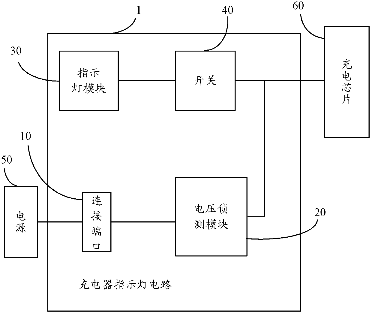
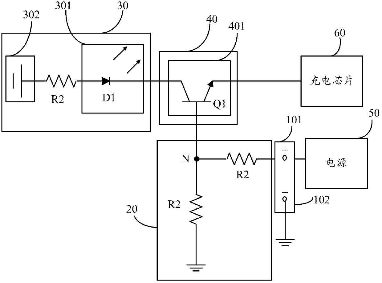
[0011] see figure 1 , is a module structure diagram of a preferred embodiment of the charger indicator circuit. The charger indicator light circuit 1 includes a connection port 10 , a voltage detection module 20 , an indicator light module 30 and a switch 40 . The connection port 10 is used to access a power source 50 . The switch 40 is externally connected to a charging chip 60 and located in the current branch where the indicator light module 30 is located, for turning on or off the current branch where the indicator light module 30 is located.

[0012] The charging chip 60 manages the charging of the battery, and generates a low-level signal when the battery meets the charging condition; and generates a high-level signal when the battery does not meet the charging condition. Specifically, the battery meeting the charging condition means that the battery is not fully charged, and the battery not meeting the charging condition means that the battery is fully charged.

[00...


PUM


Abstract

A charger indicating lamp circuit is used for indicating the charging state when a battery is charged. The circuit comprises an indicating lamp module, a voltage detection module, a charging chip and a switch. The indicating lamp module includes an indicating lamp and is used for indicating whether the charger is working normally; the voltage detection module outputs a first potential when detecting that a power supply is connected to a connection port and outputs a second potential when detecting that the charging power supply is not connected to the connection port; the charging chip outputs a low level when a battery meets charging conditions and outputs a high level when the battery does not meet the charging conditions; and the switch switches on a branch where the indicating lamp module is located when the charging chip outputs the low level and the voltage detection module outputs the first potential so as to turn on the indicating lamp, and switches off the branch where the indicating lamp module is located when the charging chip outputs the low level and / or the voltage detection module outputs the second potential so as to turn off the indicating lamp. On / off of the indicating lamp can be controlled without the use of software.

Description

technical field [0001] The invention relates to a circuit, in particular to a charger indicator circuit. Background technique [0002] At present, the general indicator light circuit of the charger is to control the light on or off of the indicator light of the charger through the soft control mode of the controller, so that the existing indicator light circuit of the charger is relatively complicated. Moreover, the existing charger indicator light circuit requires the controller to be in the working state all the time, and when the controller is in a power-off state, it cannot control the on or off of the charger indicator light. Contents of the invention [0003] In view of this, a charger indicator circuit is provided, which can control the on or off of the indicator light without using software. [0004] A charger indicator circuit is used to indicate the charging status when charging a battery, the charger indicator circuit includes a connection port for connecting t...

Claims


Application Information

Patent Timeline
Patent Type & Authority Applications(China)
IPC IPC(8): H02J7/00H02J7/02
CPCG01R31/3646H02J7/0048
Inventor 程海龙汪涛邓雪冰马晓辉李新平施用松
Owner HONG FU JIN PRECISION IND (SHENZHEN) CO LTD
Learn More