Eureka AIR delivers breakthrough ideas for toughest innovation challenges, trusted by R&D personnel around the world.

Parallel wire extruding auxiliary mould

An auxiliary mold and wire technology, which is applied in the field of parallel wire extrusion auxiliary molds, can solve the problems of easy dislocation of arrangement and irregular product shape, and achieves the effects of simple structure, easy processing and diverse material selection.

Inactive Publication Date: 2013-09-25
宁波球冠电缆股份有限公司
View PDF4 Cites 2 Cited by
  • Summary
  • Abstract
  • Description
  • Claims
  • Application Information

AI Technical Summary

Problems solved by technology

However, in the actual production process, the arrangement of multiple wire cores is prone to misalignment after entering the mold core, resulting in irregular shapes of the produced products, which cannot meet the requirements

Method used


Image

  • Parallel wire extruding auxiliary mould
  • Parallel wire extruding auxiliary mould
  • Parallel wire extruding auxiliary mould

Examples


Embodiment 1

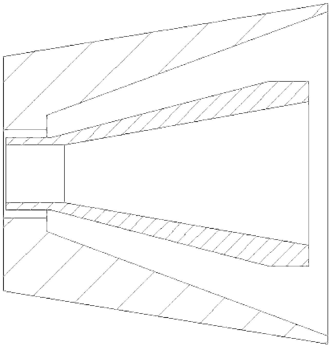
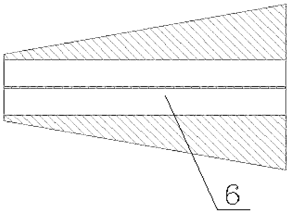
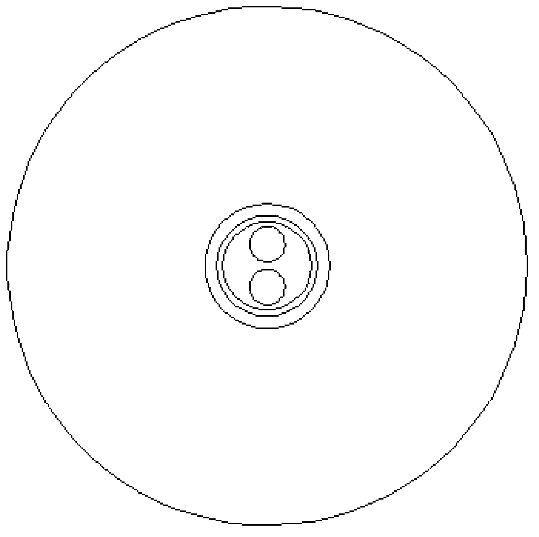
[0017] Such as Figure 2 ~ Figure 4 As shown, a parallel wire extrusion auxiliary mold includes a conventional cable mold cover 2, an auxiliary mold core 3, a conventional cable mold core 5, and a threading hole 6. The inner cavity of the conventional cable mold cover 2 is covered with a conventional Cable mold core 5, an extrusion sheath 1 is also installed on the gap between the conventional cable mold core 5 and the conventional cable mold sleeve 2, the cavity of the conventional cable mold core 5 is a tapered hole, and the tapered hole An auxiliary mold core 3 is set inside, and a plurality of threading holes 6 parallel to each other are evenly opened on the auxiliary mold core 3 .

[0018] The tapered hole of the auxiliary mold core 3 corresponding to the inner cavity of the conventional cable mold core 5 is a cone and the apex of the cone is flattened into a circular surface.

[0019] The described threading hole 6 is used for threading the cable core 4 .

[0020] Ther...


PUM


Abstract

The invention relates to a parallel wire extruding auxiliary mould which comprises an extruding protective jacket (1), a conventional cable mould sleeve (2) and a conventional cable mould core (5), wherein the conventional cable mould core (5) is sleeved on an inner cavity of the conventional cable mould sleeve (2), the extruding protective sleeve (1) is also arranged on a gap between the conventional cable mould core (5) and the conventional cable mould sleeve (2), the inner cavity of the conventional cable mould core (5) is a taper hole, an auxiliary mould core (3) is sleeved in the taper hole, and a plurality of mutually parallel thread holes (6) are uniformly formed in the auxiliary mould core (3). The parallel wire extruding auxiliary mould is simple in structure, easy to process and variable in material selection, and can meet the production demand on various kinds of flat protective jacket wires.

Description

technical field [0001] The invention belongs to the technical field of cable production devices, in particular to an auxiliary die for extrusion of parallel electric wires. Background technique [0002] The original mold for the production of flat sheathed wires is a flat exit extrusion die, and different product specifications require different sizes of molds, and must be dedicated to the mold. Moreover, the mold requires high precision in design and processing, and the mold preparation period is relatively long. However, when there are special specification requirements in urgent orders, such molds are difficult to adjust and cannot be shipped within the delivery period. [0003] To sum up the above reasons, through the analysis of the stretching characteristics of the rubber material when extruded by the extruded tube die, the extruded round tube can completely cover two or more insulated wire cores arranged in parallel by stretching. to meet the requirements of paralle...

Claims


Application Information

Patent Timeline
Patent Type & Authority Applications(China)
IPC IPC(8): B29C47/12B29C48/30
Inventor 傅伟文陈中区
Owner 宁波球冠电缆股份有限公司
Why Eureka
Eureka Blog
Learn More