
Support

A support frame and support part technology, applied in the field of support frames, can solve problems such as space occupation and easy breakage of positioning devices, and achieve the effect of strong support structure, simple structure and obvious effect

Active Publication Date: 2013-09-25
HANGZHOU ZHONGYA MACHINERY CO LTD
View PDF5 Cites 2 Cited by
  • Summary
  • Abstract
  • Description
  • Claims
  • Application Information

AI Technical Summary

Problems solved by technology

[0004] The technical purpose of the present invention is to provide a support frame that is convenient for storage and transportation and is suitable for mechanized full-automatic boxing, and solves the technical problems of easy breakage and space occupation of positioning devices in the prior art

Method used


Image

  • Support
  • Support
  • Support

Examples


Embodiment Construction

[0021] Such as Figure 4 , 5 Support frame shown is die cut from corrugated cardboard. The supporting frame is provided with a positioning part I2, a wrapping part I3 and a supporting part I4, and the three are connected as a whole and are distinguished by a crease line 5 between the three. The positioning part I2 has a rectangular structure as a whole, and the side lengths of two opposite sides are longer than the side lengths of the other opposite two sides, forming a rectangular shape. The wrapping part I3 is also in the shape of a rectangle, and is distributed on four sides of the positioning part I2. The support part I4 is also rectangular in shape, and the support part I4 is provided with two parallel crease lines 5, so that the support part I4 has a three-stage structure, and the support part I4 is also distributed on four sides of the positioning part support part I4. On either side of the positioning part I2, the crease line 5 between the wrapping part I3 and the p...


PUM


Abstract

The invention discloses a support which is of a flat platy structure. The support comprises a first locating portion, first wrapping portions and first supporting portions. The first locating portion is rectangular. The first wrapping portions and the first locating portion are connected into a whole. The first supporting portions are of three-section structures and are connected with the first locating portion into a whole. The first locating portion is connected with two first supporting portions at each long edge, and one first wrapping portion connected with the first locating portion at each long edge is located between the two first supporting portions. One first supporting portion is connected with the first locating portion at each wide edge, and the first wrapping portions connected with the first locating portion at each wide edge are located on two sides of the first supporting portion. The support is simple in structure, convenient to produce, capable of being made of environment-friendly materials, and remarkable in locating and fixing effects when in use.

Description

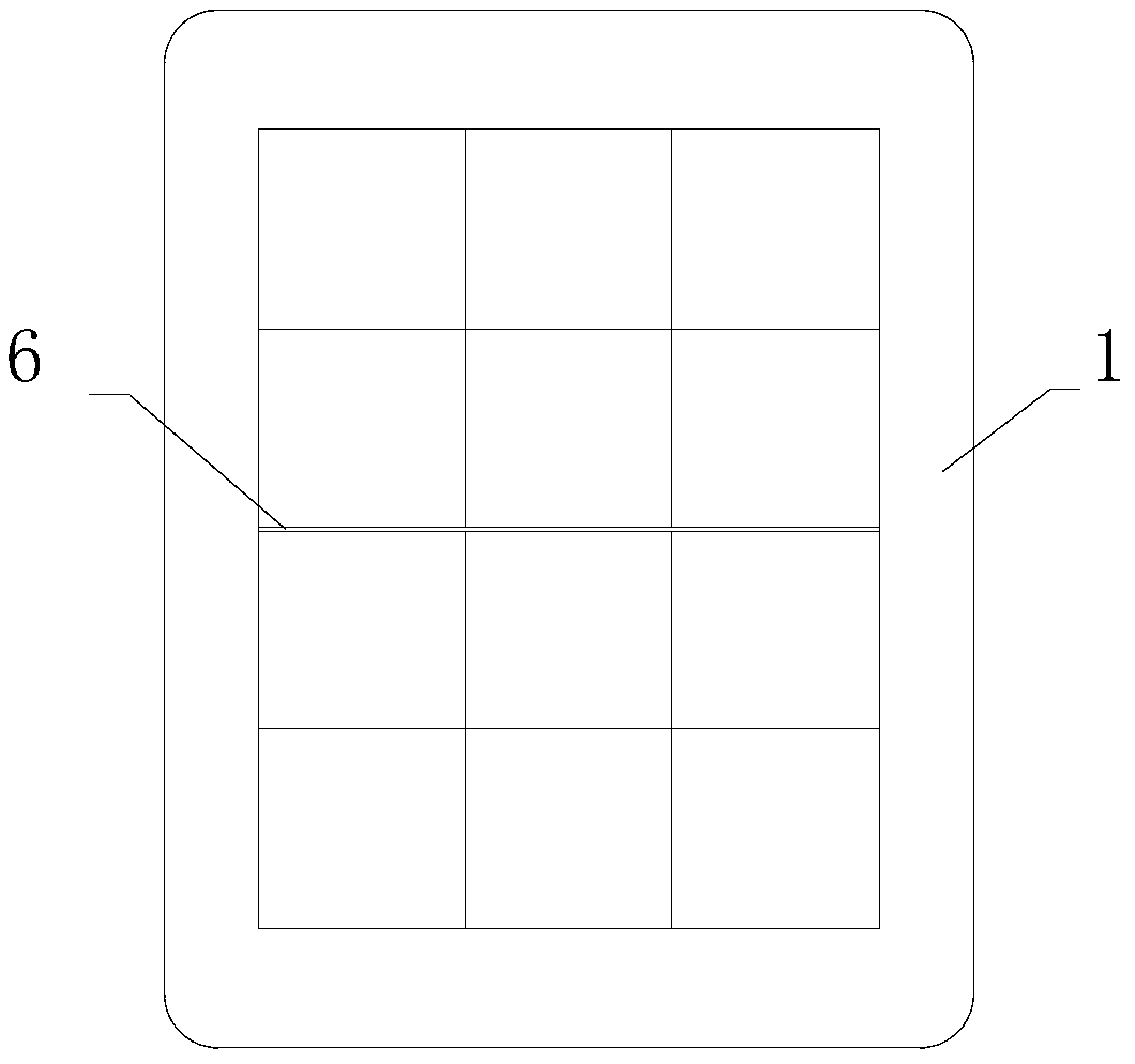
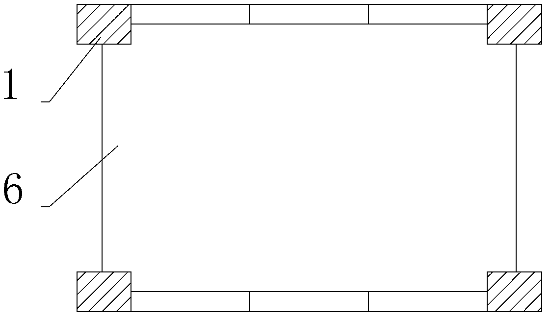
technical field [0001] The invention relates to a support frame. Background technique [0002] High-end milk products are usually filled in aseptic paper packaging (referred to as aseptic bricks). Before packing, the aseptic bricks are placed in a three-by-four or three-by-five matrix arrangement, and then placed around the placed aseptic bricks Two positioning devices are installed, and the two positioning devices are distributed up and down. In the prior art, the positioning device is a foam board with a frame structure, such as figure 1 As shown, a rectangular through hole is arranged in the middle of the foam board 1, and an array of aseptic bricks arranged in a matrix is ​​placed there. In order to enable the foam board 1 to be located on the upper and lower parts of the aseptic bricks, an interlayer 6 is placed between the arranged aseptic bricks, such as figure 2 As shown, the interlayer is rectangular as a whole, and there are right-angle notches at four right an...

Claims


Application Information

Patent Timeline
Patent Type & Authority Applications(China)
IPC IPC(8): B65D5/50
Inventor 史中伟
Owner HANGZHOU ZHONGYA MACHINERY CO LTD
Learn More