Plow discharger

A plough unloader and plough share technology, which is applied to conveyor objects, transportation and packaging, etc., can solve problems such as defects in details, and achieve the effect of changing the direction of unloading.

Inactive Publication Date: 2013-09-25
JIANGSU XINLIAN HYDRAULIC MECHANICAL & ELECTRICALCO
View PDF0 Cites 1 Cited by
  • Summary
  • Abstract
  • Description
  • Claims
  • Application Information

AI Technical Summary

Problems solved by technology

[0003] At present, as far as the plow unloader is concerned, it is mainly used for conveyor belts, and it can unload materials well through the plowshare, but there are still defects in details, so there is still room for improvement

Method used


Image

  • Plow discharger
  • Plow discharger
  • Plow discharger

Examples


Embodiment Construction

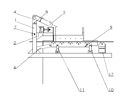
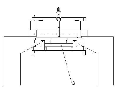
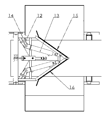
[0012] The present invention will be further described below in conjunction with accompanying drawing and specific embodiment:

[0013] Such as figure 1 , 2 As shown in and 3, a plow type unloader includes a door frame 1, a large connecting rod 2, a round connecting rod 3, a lifting cylinder seat 4, a lifting cylinder 5, a long connecting rod 6, a bearing pin 7, a boom 8, Roller frame 9, lower bracket 10, short connecting rod 11, rotary cylinder seat 12, rotary cylinder 13, plowshare 14, left plowshare plate 15, right plowshare plate 16, adjustable idler roller frame 17, the idler roller The frame 9 is connected with the door frame 1 through the long connecting rod 6, the round connecting rod 3, the large connecting rod 2, the pin shaft 7, and the suspender 8, and the roller frame 9 is connected with the lower bracket 10 through the short connecting rod 11. The lift cylinder seat 4 is bolted to the mast 1, the rotary cylinder seat 12 is welded to the plow share 14, the left ...


PUM


Abstract

The invention discloses a plow discharger. The plow discharger comprises a gantry, a big connecting rod, a round connecting rod, a lift cylinder seat, a lift cylinder, a long connecting rod, a pin shaft, a hoisting rod, a carrier roller frame, lower brackets, short connecting rods, rotating cylinder seats, rotating cylinders, colters, a left colter plate, a right colter plate and an adjustable carrier roller frame, wherein the carrier roller frame is connected to the gantry through the long connecting rod, the round connecting rod, the big connecting rod, the pin shaft and the hoisting rod, the carrier roller frame is connected to the lower brackets through the short connecting rods, the lift cylinder seat is in threaded connection with the gantry, the rotating cylinder seats are in welded connection with the colters, the left colter plate and the right colter plate are connected with the colters through long pins, and the adjustable carrier roller frame is in threaded connection with the lower brackets. The plow discharger provided by the invention can effectively discharge under various execrable conditions, and can ensure discharging of all on-site stock bins in virtue of the changeable colters, so that the all stock bins do not need other discharge manners, and the discharge direction of materials on a line belt can be changed by changing the direction of the colters.

Description

technical field [0001] The invention relates to an unloading device, in particular to a plow unloader. Background technique [0002] After a long period of development, the plow unloader has been widely used in cement, metallurgy, mining, etc. Its appearance has solved the problem of unloading materials into each silo when conveying materials on each conveyor belt. [0003] At present, as far as the plow unloader is concerned, it is mainly used for conveyor belts and can discharge materials well through the plowshare, but there are still defects in the details, so there are still things to be improved. Contents of the invention [0004] The object of the present invention is to overcome the deficiencies of the prior art and provide a plowshare variable unloader, which satisfies the three working modes of left unloading, right unloading, and double-side unloading at the same unloading place on site. [0005] The technical solution adopted in the present invention is: a ...

Claims


Application Information

Patent Timeline
IPC IPC(8): B65G47/76
Inventor 高连信周小民葛乃忠
Owner JIANGSU XINLIAN HYDRAULIC MECHANICAL & ELECTRICALCO
Why Eureka
Try Eureka