a vane pump

A technology of vane pumps and vanes, which is applied to pumps, pump controls, pump components, etc., can solve the problems of impermissible vane reversal, complex structure of vane pumps, and impact on service life, so as to facilitate processing, prevent excessive reversal, Effect of reducing noise problems

Active Publication Date: 2017-08-08
TAIZHOU HONGYI HYDRAULIC SERVO TECH CO LTD
View PDF10 Cites 0 Cited by
  • Summary
  • Abstract
  • Description
  • Claims
  • Application Information

AI Technical Summary

Problems solved by technology

[0005] The invention provides a vane pump applied to an injection molding machine with a simple structure, which can adapt to frequent shutdowns, allows the blades to reverse properly, reduces noise during the reverse rotation, and has a long service life; it solves the problems existing in the prior art The structure of the vane pump is too complicated to allow the vane to reverse, the reverse noise is large, and the technical problem is that the service life is affected

Method used


Image

  • a vane pump
  • a vane pump
  • a vane pump

Examples


Embodiment

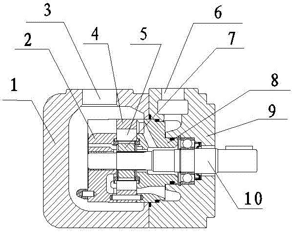
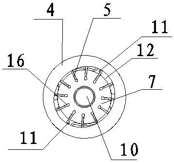
[0021] Such as figure 1 with 2 As shown, a vane pump includes a pump body, a pump core and a transmission shaft 10 located in the pump body. The pump body includes a front housing 1 and a rear housing 9 located on the left and right sides, the front housing 1 is provided with an oil suction port 3 , and the rear housing 9 is provided with an oil pressure port 6 . The pump core includes a rotor 7 which is located on the transmission shaft 10 and rotates synchronously with the transmission shaft 10. A vane groove 16 is opened on the rotor 7, and a vane 5 is inserted in the vane groove 16. A The stator 4 has an oval hole in the center of the stator 4, the stator 4 and the rotor 7 rotate coaxially, and there is a gap between the stator 4 and the rotor 7. When the vane pump works normally, one end of the vane 5 is always close to the stator 4 under the centrifugal force of the rotor 7 . An oil suction distribution plate 2 and a pressure oil distribution plate 8 are installed on ...


PUM


Abstract

The invention relates to a vane pump applied to a plastic injection machine. The vane pump comprises a pump body, wherein a transmission shaft, a rotor and a stator are arranged in the pump body; vanes are uniformly distributed between the rotor and the stator; an oil distribution disc is arranged at two sides of the rotor and comprises an oil suction distribution disc and an oil pressing distribution disc; an oil cavity is formed among the rotor, a stator, the vanes and the oil distribution disc; the oil cavity is divided into an oil suction zone, an oil pressing zone and a seal zone according to the state and function of the vane pump when the vane pump rotates positively and works; the seal zone is arranged between the oil suction zone and the oil pressing zone; an oil hole is formed in the rotor or the oil distribution disc which forms the oil suction zone. The invention provides the vane pump which is applied to the plastic injection machine, is simple in structure, capable of adapting frequent machine halts and long in service life; moderate negative rotation of the vanes is allowed and the noise is reduced when the vanes rotate negatively; the technical problem that in the prior art, an existing vane pump is too complex in structure and large in negative rotation noise, the negative rotation of the vanes are not allowed and the service life is impacted is solved.

Description

technical field [0001] The invention relates to a vane pump, in particular to a vane pump applied to injection molding machines. Background technique [0002] As we all know, the hydraulic vane pump is the power source of the hydraulic system. It has the characteristics of low noise and high pressure, and is widely used in machine tools, plastic machines, leather machinery, forging machinery, engineering machinery and other fields. [0003] In the current patent documents, there are also many introductions about vane pumps. For example, the Chinese patent: "A vane pump (CN202441597U)", including pump body, pump cover, main shaft, pump core, oil distribution plate, fixed pump cover On the pump body, the inner cavity for the pump core and the oil distribution plate is formed between the pump body and the pump cover. Between them, one end face of the oil distribution plate is in close contact with the pump core, and a compression spring is set between the other end face of the...

Claims


Application Information

Patent Timeline
Patent Type & Authority Patents(China)
IPC IPC(8): F04C2/344F04C14/06F04C15/00
Inventor 齐国兴王洪继
Owner TAIZHOU HONGYI HYDRAULIC SERVO TECH CO LTD
Why Eureka
Try Eureka