Large gear two-side bearing withdrawing machine

A large gear and unloading machine technology, applied in metal processing, metal processing equipment, manufacturing tools, etc., can solve the problem of not being able to keep the large gear stationary, and achieve the effect of filling the gaps in technology and the market, and the structure is simple and reasonable

Pending Publication Date: 2021-03-26
HUBEI HEQIANG MACHINERY DEV LIMITED BY SHARE
View PDF0 Cites 0 Cited by
  • Summary
  • Abstract
  • Description
  • Claims
  • Application Information

AI Technical Summary

Problems solved by technology

[0002] It is understood that the existing technology can only remove the large gear and the bearing together, that is, first remove the large gear and the bearing on one side, and then remove the bearing on the other side
Instead of keeping the large gear still, the bearings on both sides of the large gear can be withdrawn separately, but now the market really needs this technology and machinery that can separately withdraw the bearings on both sides of the large gear.

Method used


Image

  • Large gear two-side bearing withdrawing machine
  • Large gear two-side bearing withdrawing machine
  • Large gear two-side bearing withdrawing machine

Examples


Embodiment Construction

[0035] Embodiments of the present invention will be described below in conjunction with the accompanying drawings. It should be understood that the embodiments described here are only used to illustrate and explain the present invention, and are not intended to limit the present invention.

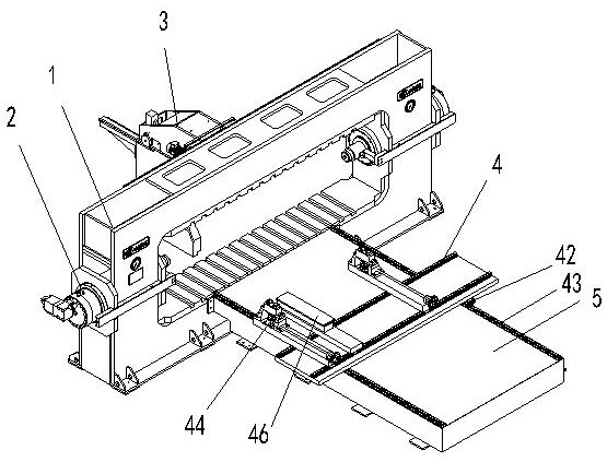
[0036] Such as Figure 1 to Figure 9 As shown, the present invention discloses a bearing unloading machine on both sides of a large gear, including a frame 1, an oil cylinder device 2, an unloading device 3, a supporting trolley 4, a supporting trolley chassis 5, and a transition tool 6;

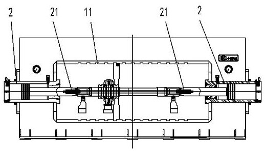
[0037] The frame 1 is in the shape of a back, and the upper and lower beams of the frame are correspondingly provided with slots 11 for inserting plates;

[0038] The oil cylinder device 2 is symmetrically arranged at both ends of the frame in the center of the coaxial line, and the oil cylinder device has a top mechanism 21;

[0039] The unloading device 3 is arranged on one side of the frame, and it h...


PUM


Abstract

A large gear two-side bearing withdrawing machine comprises a machine frame, oil cylinder devices, a withdrawing device, a material supporting trolley, a material supporting trolley chassis and a transition tool. The machine frame is in a concentric-square shape, and inserting plate grooves are correspondingly formed in an upper cross beam and a lower cross beam of the machine frame; the oil cylinder devices are coaxially and symmetrically arranged at the two ends of the machine frame in a centered manner and are provided with centre mechanisms. the withdrawing device is arranged at one side of the machine frame, a hanging seat of the withdrawing device is arranged above the upper cross beam of the machine frame, a first driving mechanism is arranged on the hanging seat, an inserting plateis arranged below the hanging seat, a second driving mechanism and a second guiding device are arranged in front of the hanging seat, the first guiding device is arranged between the hanging seat andthe inserting plate, and a rack is arranged on the inserting plate; a U-shaped opening is formed in the side of the inserting plate, and the height of the opening is larger than the diameter of a train axle; and the transition tool is a cylinder formed by fixing two halves through bolts, and a clamping groove is formed in the outer circle of the cylinder. The withdrawing machine is simple and reasonable in structure, can effectively complete withdrawing machine of bearings at the two sides of a large gear, and fills the technical and market gaps.

Description

technical field [0001] The invention relates to equipment machinery in the field of rail transportation, in particular to a machine for unloading bearings on both sides of a large gear. Background technique [0002] It is understood that in the prior art, the large gear and the bearing can only be withdrawn together, that is, the large gear and the bearing on one side are withdrawn first, and then the bearing on the other side is withdrawn. And can not keep bull gear motionless, move back the bearing on its both sides respectively, but the technology and the machinery that this can withdraw respectively the bearing on both sides of bull gear really needs in the market now. Contents of the invention [0003] In order to solve the problem of insufficient existing technology, the present invention provides a bearing unloading machine on both sides of the large gear, [0004] The utility model has a reasonable structure and can effectively complete the withdrawing and dismoun...

Claims


Application Information

Patent Timeline
Patent Type & Authority Applications(China)
IPC IPC(8): B23P19/027
CPCB23P19/027
Inventor 张霄喻国锋童俊军喻侃汪亮廖威祝朝亮
Owner HUBEI HEQIANG MACHINERY DEV LIMITED BY SHARE
Why Eureka
Try Eureka