Mining constant-resistance yielding energy-absorbing impact-resisting supporting device

A support device and anti-shock technology, which is applied in the direction of mining equipment, pillars/brackets, earthwork drilling, etc., can solve problems such as damage, support body deformation, poor impact resistance, etc., to increase applicability and give way Fast speed and high energy absorption efficiency

Active Publication Date: 2013-09-25
LIAONING TECHNICAL UNIVERSITY
View PDF10 Cites 14 Cited by
  • Summary
  • Abstract
  • Description
  • Claims
  • Application Information

AI Technical Summary

Problems solved by technology

When rock burst occurs, a large amount of elastic energy accumulated in the rock body is released instantaneously, causing violent vibrations in the goaf and the surrounding rock of the roadway, causing the bottom of the roadway, the side and the roof to fall, and even the sudden failure of the overall structure of the surrounding rock. The support body of the roadway or working face is subjected to a huge impact load instantly, resulting in deformation, damage or complete collapse of the support body, which seriously threatens the life safety of the staff and affects the normal mining of mineral resources.
[0003] At present, the support of coal mines is basically based on rigid support, that is, the rigid structural support system based on strong support. The impact resistance of rigid support equipment is often poor, and it can still maintain a relatively stable position under static mine pressure. In the support state, once the

Method used


Image

  • Mining constant-resistance yielding energy-absorbing impact-resisting supporting device
  • Mining constant-resistance yielding energy-absorbing impact-resisting supporting device
  • Mining constant-resistance yielding energy-absorbing impact-resisting supporting device

Examples


Embodiment Construction

[0024] The present invention will be further described in detail below in conjunction with the accompanying drawings and specific embodiments.

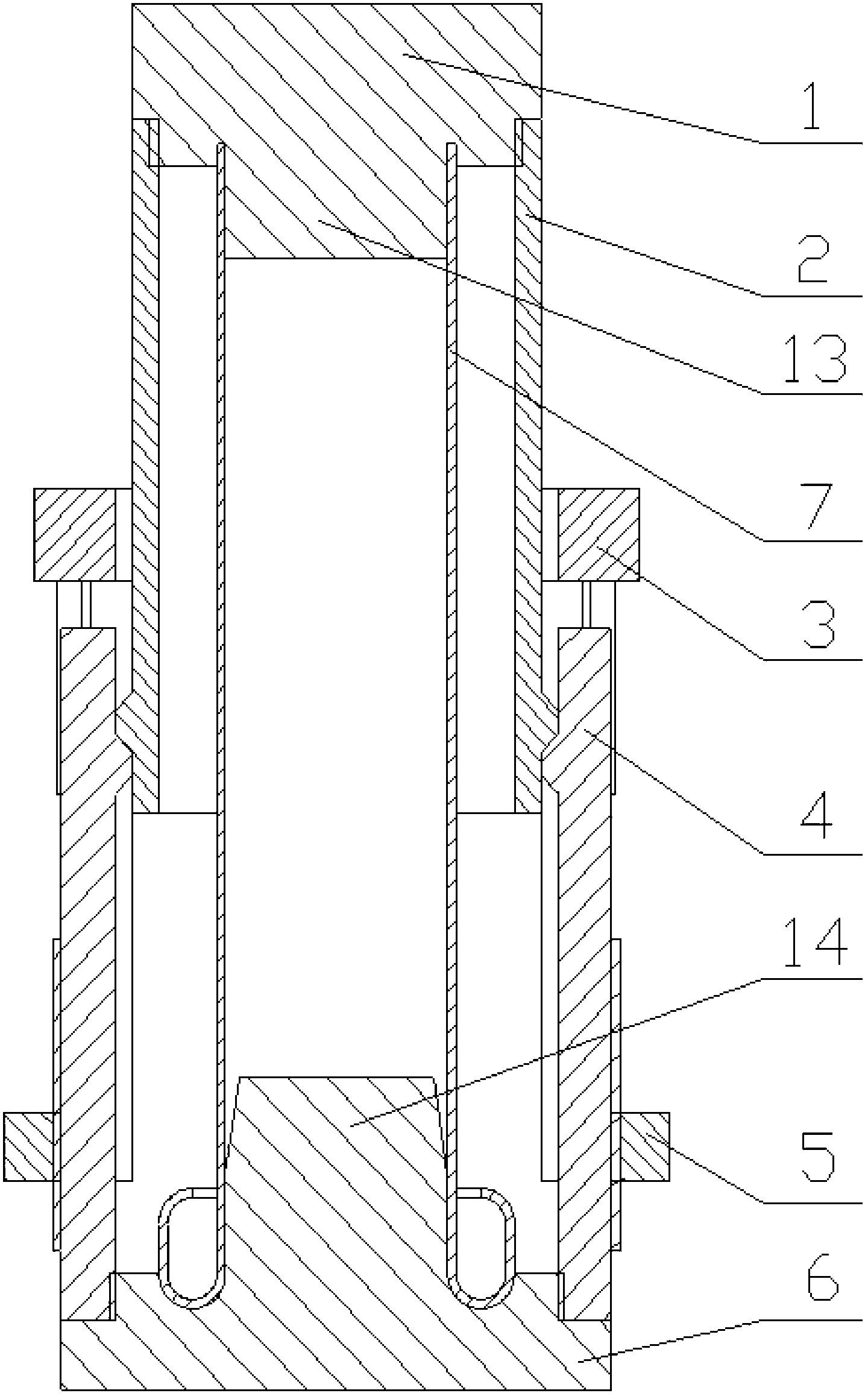
[0025] Such as figure 1 As shown, a mining constant resistance pressure-absorbing energy-absorbing anti-shock support device includes a top cover 1, a first support cylinder 2, a second support cylinder 4, a base 6, a positioning ring 3 and a constant force ring 5. The top cover 1 is connected with the upper end of the first support tube 2 by threads, the lower end of the first support tube 2 is in contact with the upper end of the second support tube 4, and the lower end of the second support tube 4 is connected with the base 6 by threads; An energy-absorbing core 7 is installed between the top cover 1 and the base 6; the positioning ring 3 is sleeved on the outside of the first support cylinder 2, and is affixed to the upper end of the outer cylinder wall of the second support cylinder 4; the fixed force The ring 5 is fixedly sleev...


PUM


Abstract

The invention discloses a mining constant-resistance yielding energy-absorbing impact-resisting supporting device and belongs to the technical field of coal mine safety supporting. The mining constant-resistance yielding energy-absorbing impact-resisting supporting device comprises a head cover, a first support barrel, a second support barrel, a base, a positioning ring and an anchoring force ring, the head cover is connected with the upper end of the first support barrel through a thread, the lower end of the first support barrel is in contact fit with the upper end of the second support barrel, the lower end of the second support barrel is connected with the base through the thread, an energy-absorbing core is mounted between the roof and the base, the positioning sleeve is sleeved outside the first support barrel and fixedly connected with the upper end of the outer wall of the second support barrel, and the anchoring force ring is fixedly sleeved on the middle-lower portion of the outer wall of the second support barrel. Yielding and energy absorption can be realized by the aid of outward turning of the barrel walls after the energy-absorbing core is under stress, and the mining constant-resistance yielding energy-absorbing impact-resisting supporting device is simple in structure, rapid in response, constant in resistance, large in deformation amplitude, high in energy-absorbing efficiency and capable of realizing quick yielding and pressure releasing under rock burst.

Description

technical field [0001] The invention belongs to the technical field of coal mine safety support, and in particular relates to a mine-used constant-resistance pressure-absorbing energy-absorbing anti-shock support device. Background technique [0002] Rock burst is the main dynamic disaster in coal mines, and it is also a worldwide mining problem. When rock burst occurs, a large amount of elastic energy accumulated in the rock body is released instantaneously, causing violent vibrations in the goaf and the surrounding rock of the roadway, causing the bottom of the roadway, the side and the roof to fall, and even the sudden failure of the overall structure of the surrounding rock. The support body of the roadway or working face is subjected to a huge impact load instantly, resulting in deformation, damage or complete collapse of the support body, which seriously threatens the life safety of the staff and affects the normal mining of mineral resources. [0003] At present, the...

Claims


Application Information

Patent Timeline
IPC IPC(8): E21D15/16
Inventor 潘一山肖永惠马箫李忠华徐连满李国臻崔乃鑫
Owner LIAONING TECHNICAL UNIVERSITY
Why Eureka
Try Eureka