
An anti-shock bracket with corrugated surface

A pattern and twist technology, applied in shaft lining, tunnel lining, underground chamber, etc., can solve problems such as poor toughness of curved beams, damage to support body, safety accidents, etc., to ensure connection stability and avoid connection The effect of failure

Inactive Publication Date: 2016-04-06
LIAONING TECHNICAL UNIVERSITY
View PDF7 Cites 4 Cited by
  • Summary
  • Abstract
  • Description
  • Claims
  • Application Information

AI Technical Summary

Problems solved by technology

When rock burst occurs, the damaged surrounding rock will have a violent impact on the support body, causing the load on the support body to increase suddenly, exceeding the static pressure by several times, ten times or even greater, often causing the support body to burst. local damage, deformation or overall collapse damage, which poses a serious threat to the safety of underground workers and production equipment
[0003] At present, the most widely used roadway support is U-shaped steel support, which is mostly composed of three-section, four-section or six-section arc-shaped beams overlapping each other, and forms an arch support or a ring support ring. The two adjacent curved beams are simply hooped by a cable, but this traditional U-shaped steel bracket still has obvious defects. Among them, the toughness of the curved beams with smooth surfaces is generally poor, resulting in the yield of the curved beams. The positional energy absorption is very poor, and the support does not have the function of quickly giving way to absorb energy. Once the impact ground pressure occurs, the part of the arc beam is easy to break or the joint of the cable is broken, which will eventually lead to the overall collapse of the support and support failure, resulting in a safety accident

Method used


Image

  • An anti-shock bracket with corrugated surface
  • An anti-shock bracket with corrugated surface
  • An anti-shock bracket with corrugated surface

Examples


Embodiment Construction

[0021] The present invention will be further described in detail below in conjunction with the accompanying drawings and specific embodiments.

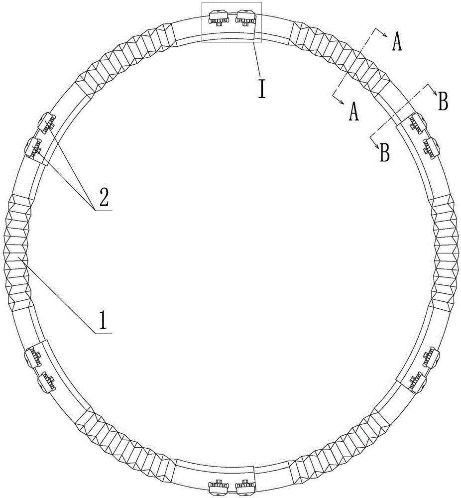
[0022] like figure 1 , 2 , 3, 4, 5, 6, and 7, a kind of anti-shock support with corrugated surface, including several arc beams 1 and connecting members 2 between the beams, and the several arc beams 1 are overlapped end to end to form a closed Ring, and every two adjacent arc-shaped beams 1 are connected by connecting members 2 between beams;

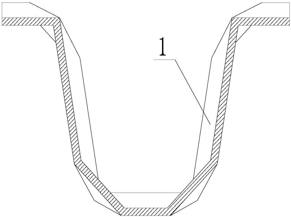
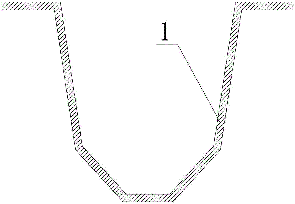
[0023] The arc-shaped beam 1 adopts a U-shaped cross-section structure, the middle section of the arc-shaped beam 1 is set as a corrugated profile structure, and the two ends of the arc-shaped beam 1 are set as a smooth profile structure;

[0024] The inter-beam connecting member 2 includes a top cover 3, a base 4 and a W-shaped elastic fastener 5, and the number of inter-beam connecting members 2 between every two adjacent arc-shaped beams 1 is two, and the first inter-beam The top cover 3...


PUM


Abstract

An anti-collision support with a corrugated face belongs to the technical field of coal mine roadway supporting. Compared with the U-shaped steel support in the prior art, a corrugated face structure is additionally arranged on the middle section of an arc-shaped beam of the support, due to the corrugated face structure, the whole or part of the support can contract rapidly when encountering rock burst, the avoidance of surrounding rock is realized by the contraction of the support, and further the avoidance and energy consumption of the whole support are realized; according to the anti-collision support provided by the invention, the traditional mode of connecting two adjacent arc-shaped beams by a clamp cable is abandoned, a W-shaped elastic strip buckle is adopted to be a limiting member and realize composure control, and when rock burst is encountered, connecting components between the beams can dislocate mutually along with the two adjacent beams and follow the beams to move, so that the failure of connection at the connecting part of the two adjacent arc-shaped beams is avoided, meanwhile the contraction of the whole support is facilitated, and the stability of connection is guaranteed.

Description

technical field [0001] The invention belongs to the technical field of coal mine roadway support, and in particular relates to an anti-scour support with a corrugated surface applied to coal and rock roadways. Background technique [0002] my country's energy structure is still dominated by coal consumption, and most of my country's coal resources are buried in the depths below a kilometer, so it is an inevitable trend for coal mining to go deep. But at the same time, deep mining brings serious underground disasters. As one of the major dynamic disasters in coal mines, rock burst has caused a large number of property losses and casualties in recent years. When rock burst occurs, the damaged surrounding rock will have a violent impact on the support body, causing the load on the support body to increase suddenly, exceeding the static pressure by several times, ten times or even greater, often causing the support body to burst. Local damage, deformation or overall collapse a...

Claims


Application Information

Patent Timeline
Patent Type & Authority Patents(China)
IPC IPC(8): E21D11/20E21D11/22
Inventor 陈凯肖永惠刘歆妍栾丽君孙建强曹娟李如玉付志国
Owner LIAONING TECHNICAL UNIVERSITY
Learn More