
Supersonic non-uniform incoming flow maximum thrust nozzle and its wall surface determination method

A technology that determines the maximum thrust and method, and is applied to jet propulsion devices, machines/engines, etc. to achieve the effect of increasing thrust

Active Publication Date: 2015-12-02
NAT UNIV OF DEFENSE TECH
View PDF5 Cites 0 Cited by
  • Summary
  • Abstract
  • Description
  • Claims
  • Application Information

AI Technical Summary

Problems solved by technology

[0007] Under the condition of uniform incoming flow, the above design method can realize the maximum thrust of the nozzle, but the incoming flow of the supersonic tail nozzle is non-uniform, and the existing methods cannot be directly extended to the design of the non-uniform flow nozzle surface curve

Method used


Image

  • Supersonic non-uniform incoming flow maximum thrust nozzle and its wall surface determination method
  • Supersonic non-uniform incoming flow maximum thrust nozzle and its wall surface determination method
  • Supersonic non-uniform incoming flow maximum thrust nozzle and its wall surface determination method

Examples


Embodiment Construction

[0037] The embodiments of the present invention will be described in detail below with reference to the accompanying drawings, but the present invention can be implemented in many different ways defined and covered by the claims.

[0038] According to an embodiment of the present invention, the wall surface of the supersonic non-uniform incoming flow maximum thrust nozzle is determined by the following determination method.

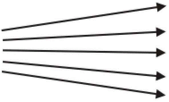
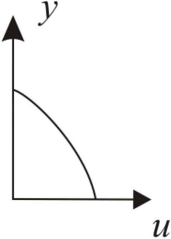
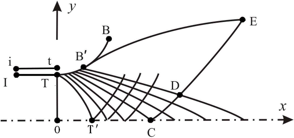
[0039] combine figure 1 with figure 2 As shown, first, go to step S1: determine the initial boundary of the supersonic non-uniform incoming flow maximum thrust nozzle according to the non-uniform incoming flow parameters. Specifically, the non-uniform incoming flow parameters at the nozzle inlet are determined by numerical simulation or experimental measurement, where the incoming flow parameters include flow angle, velocity, temperature and pressure. These four parameters can be expressed by the function of coordinate y in turn: θ=θ(y), V=V(y), T=T(y)...


PUM


Abstract

The invention provides a supersonic non-uniform inflow maximum-thrust nozzle and a wall determination method therefor. The wall determination method for the supersonic non-uniform inflow maximum-thrust nozzle includes the steps of S1, determining an initial boundary of the supersonic non-uniform inflow maximum-thrust nozzle according to non-uniform inflow parameter; S2, determining a core area of the supersonic non-uniform inflow maximum-thrust nozzle according to the initial boundary by a method of characteristics; S3, performing iterative solution in the core area to determine wall profile of the supersonic non-uniform inflow maximum-thrust nozzle according to the principle of conservation of mass and the method of characteristics; and S4, determining the wall of the supersonic non-uniform inflow maximum-thrust nozzle according to the wall profile of the supersonic non-uniform inflow maximum-thrust nozzle. The supersonic non-uniform inflow maximum-thrust nozzle and the wall determination method therefor have the advantage that the maximum-thrust nozzle applicable to supersonic non-uniform inflows can be produced.

Description

technical field [0001] The invention relates to the field of aerodynamic design, more specifically, to a supersonic non-uniform incoming flow maximum thrust nozzle and a method for determining its wall surface. Background technique [0002] For hypersonic vehicles using scramjet engines, the ramjet resistance of scramjet engines is very large, and the ratio of total thrust to net thrust increases from 1 to 10 for traditional air-breathing engines. The exhaust nozzle is the main part of the engine to generate thrust. When the flight Mach number is 6.0, the thrust generated by it can account for about 70% of the total thrust of the engine. It is not difficult to see that the design of the exhaust nozzle will vary. directly affects the performance of the entire engine. The paper "ExhaustNozzleContourforOptimumThrust" (G.V.R.Rao, JetPropulsion, Vol.28, No.6June1958) proposed a maximum thrust nozzle design method based on uniform incoming flow. The design process of this method ...

Claims


Application Information

Patent Timeline
Patent Type & Authority Patents(China)
IPC IPC(8): F02K1/00
Inventor 赵玉新郭善广王振国梁剑寒
Owner NAT UNIV OF DEFENSE TECH
Learn More