
manipulating equipment

A technology for manipulating equipment and pressure sleeves, applied to mechanical equipment, valve operation/release devices, valve details, etc., can solve problems such as user slipping, difficulty in rotating or swinging joints, and achieve long-term effects

Active Publication Date: 2016-12-28
HANS GROHE GMBH & CO KG
View PDF9 Cites 0 Cited by
  • Summary
  • Abstract
  • Description
  • Claims
  • Application Information

AI Technical Summary

Problems solved by technology

Manipulation of swivel or oscillating joints can be difficult if the possibility of soap suds on the user's hands is considered
user may slip

Method used


Image

  • manipulating equipment
  • manipulating equipment
  • manipulating equipment

Examples


Embodiment Construction

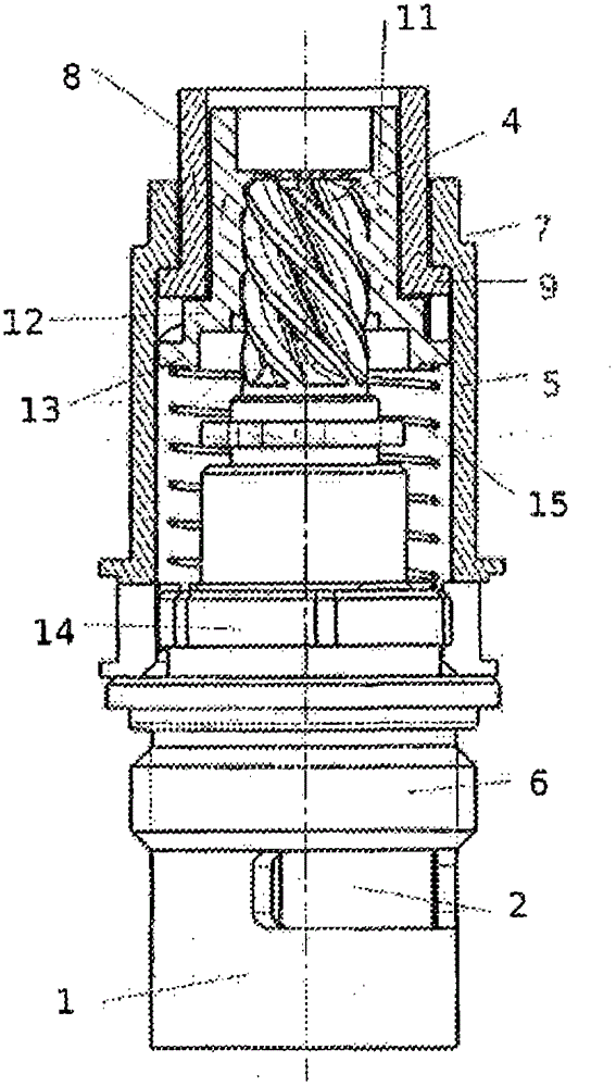
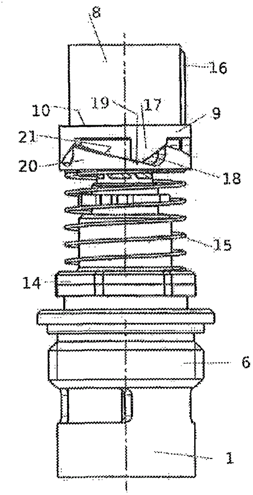
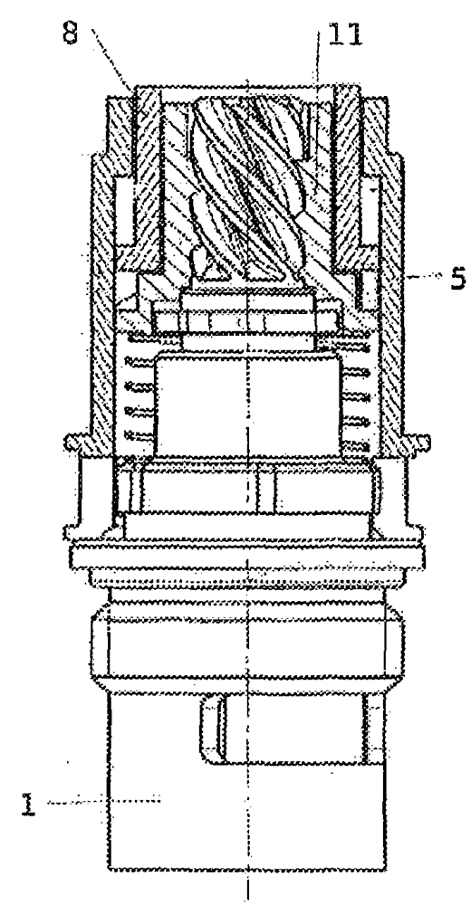
[0039] figure 1 Shown is a partial sectional view of the structure of an actuating device for a sanitary rotary valve. The valve has a valve housing 1 with a valve opening 2 . The valve housing 1 has a region with an external thread 3 , with which the valve housing can be screwed into a receptacle for a sanitary ware or shower or the like. A valve body with a rotating lead screw is rotatably supported inside the valve housing 1 . These details are not shown here. exist figure 1 In this case, the upper end of the rotary screw protrudes from the valve housing 1 and is provided with a steep thread (Steilgewinde) 4 there.

[0040] exist figure 1 In the upper area, the valve housing 1 is provided with a cage ( )5. The cage 5 is supported on a flange 6 of the valve housing 1 . The cage 5 forms a step 7 in the region of its end facing away from the valve housing 1 . The cage forms a cylindrical structure, in the example shown, both on its outside and on its inside, above an...


PUM


Abstract

The actuating device has a rotary spindle that is rotatably connected with a valve closure body, where a sharp thread (4) is arranged at a shaft of the rotary spindle. A rotatably and axially slidably supported rotary sleeve (11) stands in interference with the sharp thread. An axially slidably but non-rotatably pressure sleeve (8) is connected in a direction with the rotary sleeve. A pressure spring (15) is formed for acting upon the pressure sleeve in an initial position. A reverse rotation lock acts between the rotary sleeve and the pressure sleeve.

Description

technical field [0001] The invention relates to an operating device for a sanitary rotary valve. Background technique [0002] Plumbing fixtures usually have valves so that the flow of water is turned on or off, but can also be used to switch between different flows. For example, there are hand showers or overhead showers that can be switched between two types of water jets. Such valves are often rotary or swing valves, ie the valve body rotates or oscillates about a usually fixed axis. The associated actuating part is usually arranged such that the same movement, ie turning or pivoting the actuating part, must be carried out when the valve is actuated. [0003] Such a valve can be arranged, for example, on the handle of the hand shower. If it is taken into account that the user may already have soap suds on his hands, then the actuation of the swivel or swivel joint becomes difficult. User may slip and fall. Contents of the invention [0004] The object of the presen...

Claims


Application Information

Patent Timeline
Patent Type & Authority Patents(China)
IPC IPC(8): F16K31/44
CPCF16K31/504F16K31/60
Inventor J·格罗斯A·哈恩
Owner HANS GROHE GMBH & CO KG
Learn More