Indoor unit of duct air conditioner

A ducted air conditioner and indoor unit technology, which is applied in air conditioning systems, heating methods, space heating and ventilation, etc., can solve the problems of airflow pressure loss, affecting air conditioning performance, and low air conditioning efficiency, and achieve simple structure and improved air conditioning. Efficiency and reduction of airflow pressure loss

Active Publication Date: 2013-09-25
QINGDAO HISENSE HITACHI AIR CONDITIONING SYST
View PDF7 Cites 12 Cited by
  • Summary
  • Abstract
  • Description
  • Claims
  • Application Information

AI Technical Summary

Problems solved by technology

[0003] The noise of the ducted air conditioner indoor unit mainly comes from the aerodynamic noise of the cross-flow fan. The cross-flow fan composed of the impeller and the motor driving the impeller is usually located directly above the lower return air outlet. When the ducted air conditioner indoor unit uses When the lower return air is operated, the noise is easily transmitted to the room through the lower return air outlet, and simply shifting the position of the lower return air outlet from directly below the cross-flow fan cannot produce obvious noise reduction effects
[0004] At present, in the design of the indoor unit of the ducted air conditioner, the noise of the air conditioner is mainly reduced by adding multiple sets of partitions in the casing. The S-shaped channel is formed in the casing to achieve the purpose of reducing noise, but when the airflow passes through the casing with multiple sets of partitions, it is easy to cause serious airflow pressure loss. For ducted air conditioners with low boosting capacity For the cross-flow fan of the indoor unit, severe airflow pressure loss will affect the performance of the entire air conditioner, making the air conditioner less efficient

Method used


Image

  • Indoor unit of duct air conditioner

Examples


Embodiment Construction

[0018] In order to make the object, technical solution and advantages of the present invention clearer, the present invention will be described in further detail below with reference to the accompanying drawings and preferred embodiments. However, it should be noted that many of the details listed in the specification are only for readers to have a thorough understanding of one or more aspects of the present invention, and these aspects of the present invention can be implemented even without these specific details.

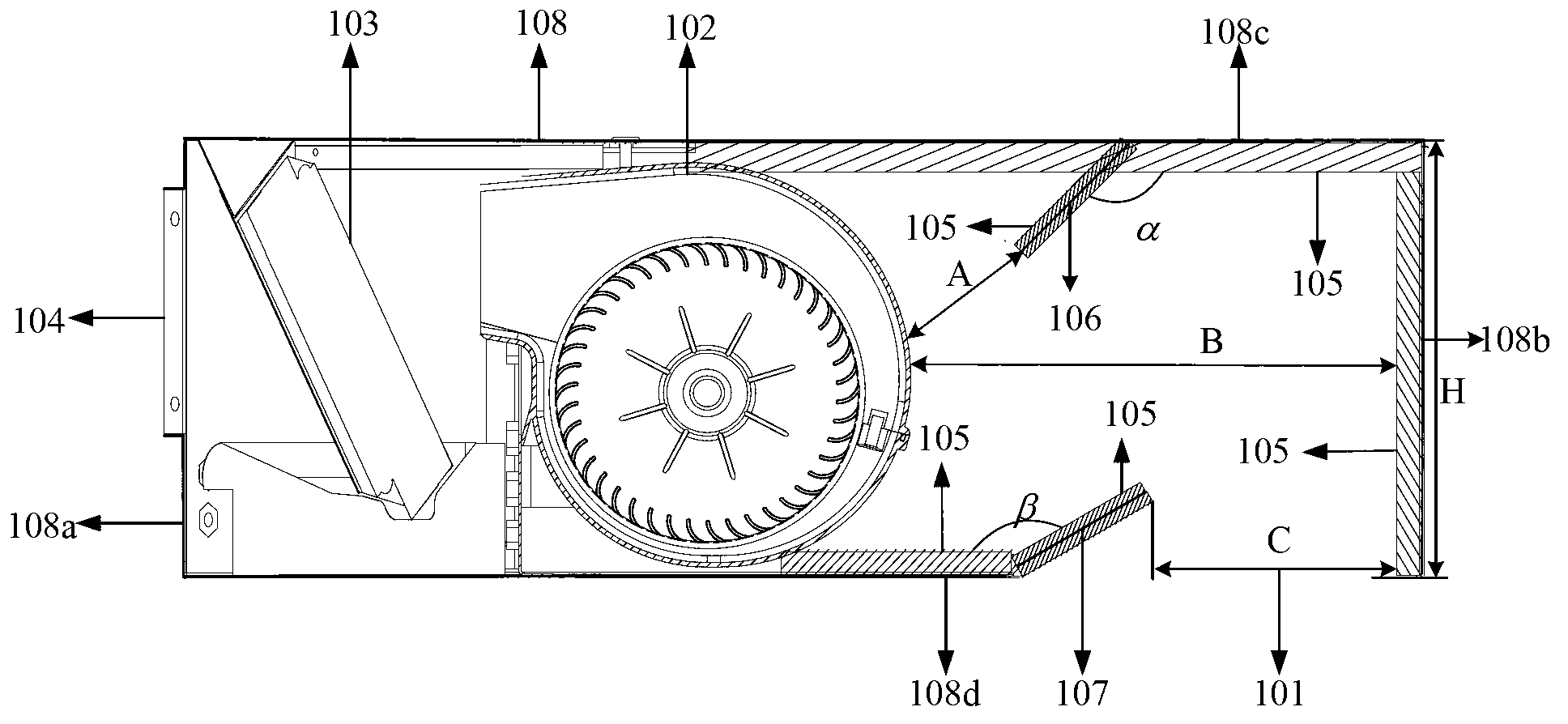
[0019] At present, the indoor unit of the ducted air conditioner generally adopts the method of placing multiple sets of partitions in the housing to reduce the noise generated by the cross-flow fan. When the indoor air flow passes through the multi-stage partitions, it will cause serious pressure loss. For cross-flow fans with low boosting capacity, serious pressure loss will affect the performance of the entire ducted air conditioner indoor unit.

[0020] In th...


PUM


Abstract

The invention discloses an indoor unit of a duct air conditioner. The indoor unit comprises a shell, a cross-flow fan, a heat exchanger, sound absorbing layers, a first sound-absorbent partition, and a second sound-absorbent partition. The shell comprises a front board, a rear board, a top board, and a bottom board. The cross-flow fan, the heat exchanger, the sound absorbing layer, the first sound-absorbent partition and the second sound-absorbent partition are disposed in the shell. An air passage is formed between an air inlet and a lower return air hole. The cross-flow fan is disposed in the left air passage above the lower return air hole. The heat exchanger is disposed in the left air passage of the cross-flow fan. One sound absorbing layer is attached to the surface of the inner wall of a right top board of the cross-flow fan, and the first sound-absorbent partition is disposed on the inner wall of the top board on the upper left of the lower return air hole. The other sound absorbing layer is attached to the surface of the inner wall of a right bottom board of the cross-flow fan, and the second sound-absorbent partition is disposed on the inner wall of the bottom board adjacent to the left of the lower return air hole. The indoor unit in application has the advantages that air conditioner noise can be reduced, pressure loss of airflow in the air passage can be reduced and air conditioner efficiency can be improved.

Description

technical field [0001] The invention relates to the technical field of air conditioners, in particular to an air duct type air conditioner indoor unit. Background technique [0002] Since the ducted air-conditioning indoor unit can circulate the indoor air by driving it to achieve high-efficiency indoor cooling or heating, it is mostly installed in hotels, schools, office buildings and other places that have high requirements on the indoor environment. However, the noise generated by the ducted air conditioner indoor unit is likely to affect users when it is running. Therefore, in the design of the ducted air conditioner indoor unit, it is particularly important to reduce the noise generated by the ducted air conditioner indoor unit by optimizing and improving the equipment. important. [0003] The noise of the ducted air conditioner indoor unit mainly comes from the aerodynamic noise of the cross-flow fan. The cross-flow fan composed of the impeller and the motor driving t...

Claims


Application Information

Patent Timeline
Patent Type & Authority Applications(China)
IPC IPC(8): F24F1/00F24F13/24
Inventor 张仁亮姜志成崔明进士干泰
Owner QINGDAO HISENSE HITACHI AIR CONDITIONING SYST
Why Eureka
Try Eureka