Lengthways outer wing type heat exchange tube

A heat exchange tube, vertical technology, applied in the field of heat exchange tubes, to achieve the effect of simple integrated structure, good quality and smooth flow

Inactive Publication Date: 2013-09-25
JIANGYAN YONGSHENG COOLING EQUIP MFG
View PDF10 Cites 1 Cited by
  • Summary
  • Abstract
  • Description
  • Claims
  • Application Information

AI Technical Summary

Problems solved by technology

[0003] The present invention mainly aims at the deficiency of the existing jacket finned heat exchange tube, and proposes a longitudinal outer finned heat exchange tube with simple structure, easy manufacture, bump resistance, easy installation and no influence on the longitudinal flow of evaporating liquid

Method used


Image

  • Lengthways outer wing type heat exchange tube
  • Lengthways outer wing type heat exchange tube
  • Lengthways outer wing type heat exchange tube

Examples


Embodiment 1

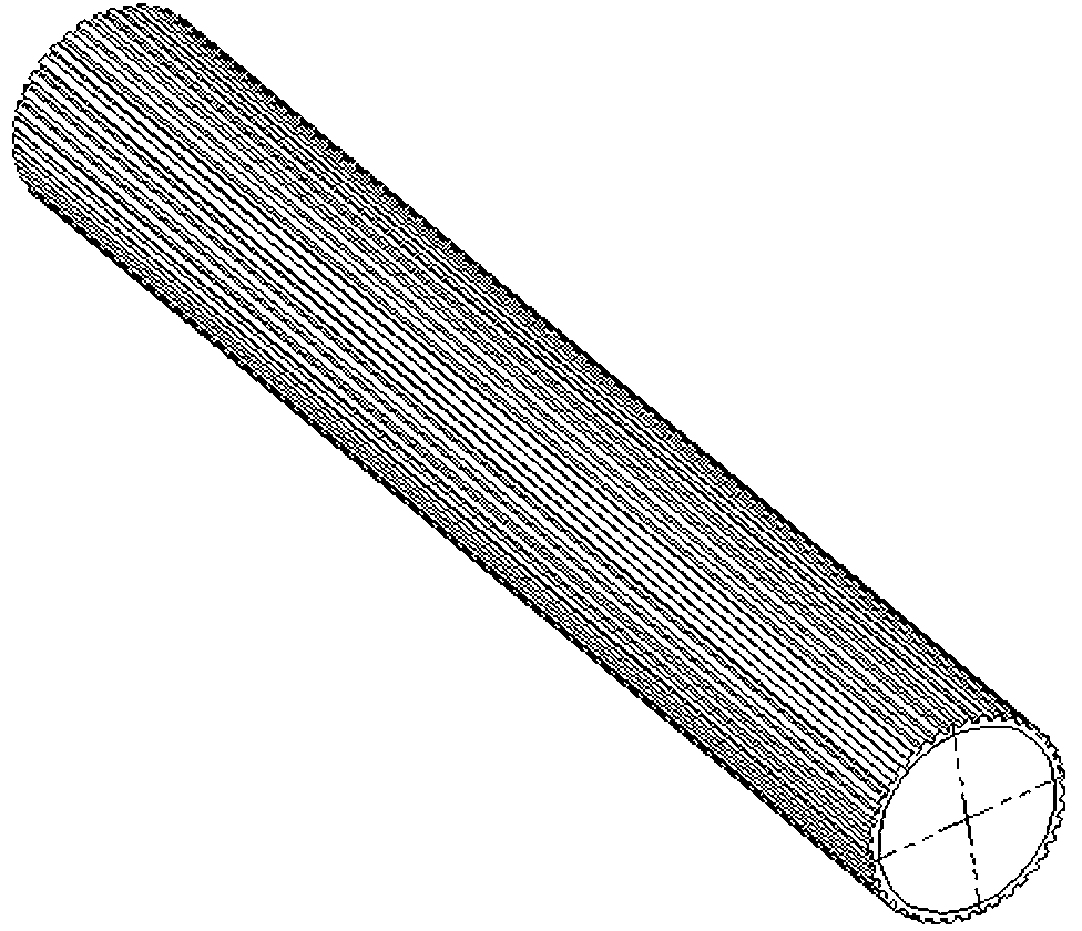
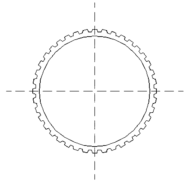
[0021] figure 1 The longitudinal outer-finned heat exchange tube shown is integrally composed of a tube body and protruding fins. The tube body is a round tube, and longitudinal fins are evenly distributed on the circumference of the outer wall, and the integrated fins are equal in length and homogeneous to the tube body. This example figure 2 As shown, the diameter of the circular tube is 12mm, and the longitudinal fins are evenly distributed on the circumference of the outer wall, the distance between adjacent fins is 2.0mm, the transverse section of the fins is trapezoidal, and the height of the fins is 0.5mm. In the present invention, the longitudinal fins and the tube body are integrally drawn, and the protruding longitudinal fins are evenly distributed on the outer wall of the tube. In addition to significantly increasing the heat exchange area, the biggest positive effect is that the longitudinal fins and the evaporating liquid flow direction Consistent, there is no ...

Embodiment 2

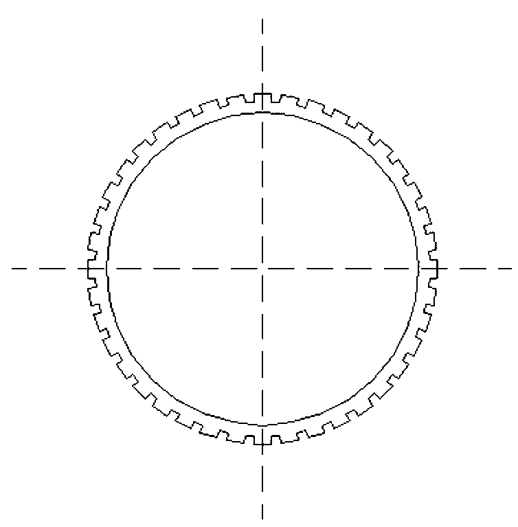
[0023] The three-dimensional structure of this embodiment is the same as that of Embodiment 1, only the cross-section of the longitudinal fins and the diameter of the pipe body are different. In this embodiment, the diameter of the pipe body is 22 mm. Due to the large diameter of the pipe body and the large amount of heat exchange, it is evenly distributed on the circumference of the outer wall of the pipe like image 3 For the rectangular longitudinal fins shown, the distance between adjacent fins is 0.4mm, the height of the fins is 0.8mm, and the transverse section of the fins is rectangular. The positive effect after application is similar to that of Example 1, although the shape of the transverse cross-section of the longitudinal fins is different.

[0024] The invention achieves an integrated structure by uniformly distributing longitudinal fins on the outer wall of the tube, which greatly facilitates installation in the manufacturing process, and improves heat exchange e...


PUM


Abstract

The invention discloses a lengthways outer wing type heat exchange tube. The lengthways outer wing type heat exchange tube is integrally composed of a tube body and outwards convex wing strips, wherein the lengthways wing strips are uniformly arranged on the circumference of the outer wall of the tube body; the wing strips in an integrated structure are same in length and quantity as the tube body. As the outwards convex lengthways wing strips are uniformly arranged on the circumference of the outer wall of the tube body, the lengthways outer wing type heat exchange tube has the maximum positive effect is that: the lengthways wing strips are in consistence with the flow direction of an evaporated liquor, no liquor resistance exists when the evaporated liquor flows, no retention phenomenon exists, and the heat exchange efficiency of the evaporated liquor is increased by more than 30% besides a heat exchange area is increased obviously. The integral structure of the lengthways wing strips and the tube body has a certain rigidity and a strong anti-bumping capability, is good for installation work in a manufacturing process, and improves work efficiency.

Description

technical field [0001] The invention relates to a heat exchange tube, in particular, the invention relates to a longitudinal outer fin heat exchange tube. Background technique [0002] The vertical evaporative condenser is one of the most widely used heat exchange devices in the market today. The heat exchange efficiency of this type of condenser mainly depends on the heat exchange tube structure. In order to improve the heat exchange efficiency, the vertical evaporative condenser is usually equipped with heat exchange tubes with jacket fins, and the heat exchange tubes with conventional structure are covered with thin plate fins, which can greatly increase the heat exchange area and improve heat exchange efficiency . Although the prior art has a simple structure and is easy to manufacture, the purpose of improving heat exchange efficiency is fully achieved. However, the fins set on the outer wall of the heat exchange tube are radially outward, and the densely arranged fin...

Claims


Application Information

Patent Timeline
IPC IPC(8): F28F1/16
Inventor 景文明矫明周俊卿林俊沐宝华黄爱国
Owner JIANGYAN YONGSHENG COOLING EQUIP MFG
Why Eureka
Try Eureka