
Communication cable detector

A technology for communication cables and detectors, which is applied to measuring devices, using stable tension/pressure to test the strength of materials, instruments, etc. It can solve the problems of inaccurate data, reduced efficiency of cable detection, and cumbersome cable installation steps. Achieve fast and efficient cable installation, convenient and accurate detection, uniform and efficient push and pull force

Inactive Publication Date: 2020-09-25
杭州三泽科技有限公司
View PDF0 Cites 0 Cited by
  • Summary
  • Abstract
  • Description
  • Claims
  • Application Information

AI Technical Summary

Problems solved by technology

[0004] The purpose of the present invention is to provide a communication cable detection machine to solve the problem that the traditional detection of the cable tensile force proposed in the above-mentioned background technology is to use a large-scale machine to operate, so that it is bulky and difficult to transport and move. It brings inconvenience, and at the same time, the cumbersome steps when installing the cable greatly delay the detection time, thereby greatly reducing the efficiency of the detection cable, and when stretching, one direction is used to squeeze and stretch, so that the force of the stretch Inhomogeneity leads to the inaccuracy of the detected data

Method used


Image

  • Communication cable detector
  • Communication cable detector
  • Communication cable detector

Examples


Embodiment Construction

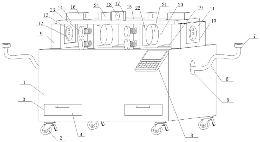
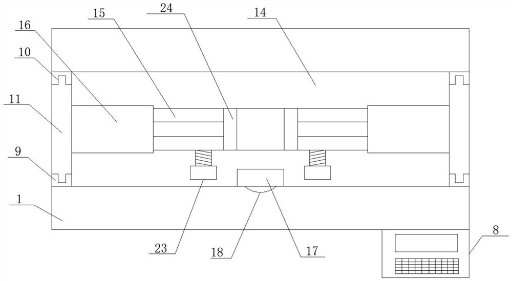
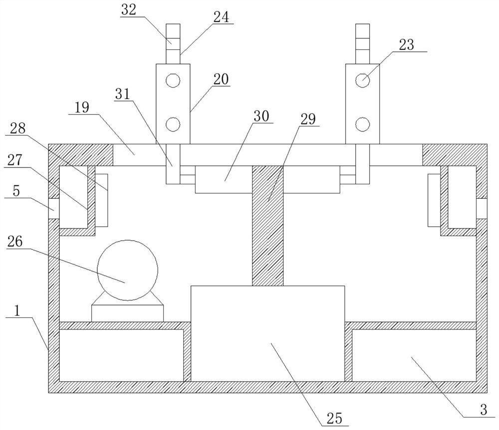
[0027] see Figure 1-2 , in the embodiment of the present invention, a kind of communication cable detection machine comprises main box body 1, and the bottom surface bolt of main box body 1 is connected with moving roller 2, and one side of main box body 1 is provided with drawer groove 3 horizontally and symmetrically, drawer The inner side of the groove 3 is horizontally plugged with a storage drawer 4, and the number of moving rollers 2 is multiple, and the plurality of moving rollers 2 are respectively fixed on the bottom surface of the main box body 1 near the edge and the center, and the drawer groove 3 is horizontal. Set on one side of the main box body 1 close to the two ends of the bottom surface, the drawer grooves 3 extend horizontally through the outer side of the main box body 1 to the inside, and the number of storage drawers 4 is consistent with the number of drawer grooves 3, and The two sides of the main box body 1 are symmetrically provided with clamping slo...


PUM


Abstract

The invention discloses a communication cable detection machine, and relates to the field of communication cables. The machine comprises a main box body, wherein the bottom surface of the main box body is in bolted connection with moving rollers; drawer grooves are horizontally and symmetrically formed in one side edge of the main box body; a storage drawer is horizontally inserted into the innerside edge of the drawer groove; clamping groove holes are symmetrically formed in the two side edges of the main box body; a transmission line is inserted into the inner side edge of the clamping groove hole; one end of the transmission line is fixedly sleeved with a butt joint; a control panel is obliquely welded to one side edge of the main box body. The top surface of the main box body is vertically and upwards connected with a side supporting plate through a bolt; and clamping grooves are formed in the side edges of the side supporting plates. The machine is integrated in design, simple instructure and convenient to operate; a push-pull force is more uniform and efficient under the multi-direction pushing effect; meanwhile, detection is more direct and efficient, detection becomes convenient, rapid and accurate, detection is more complete and rapid through more intelligent design, and the detection efficiency is greatly improved.

Description

technical field [0001] The invention relates to the technical field of communication cables, in particular to a communication cable detection machine. Background technique [0002] Communication cable refers to the cable used for short-distance audio communication and long-distance high-frequency carrier and digital communication and signal transmission. It is one of the five major cable products in China. According to the purpose and scope of use of communication cables, it can be divided into six series of products, namely, local communication cables (including paper insulated local telephone cables, polyolefin insulated polyolefin sheathed local telephone cables), long-distance symmetrical cables (including paper insulated local telephone cables) Insulated high and low frequency long-distance symmetrical cables, copper core foam polyethylene high and low frequency long-distance symmetrical cables and digital transmission long-distance symmetrical cables), coaxial cables (...

Claims


Application Information

Patent Timeline
Patent Type & Authority Applications(China)
IPC IPC(8): G01N3/10
CPCG01N3/10G01N2203/0003G01N2203/0017G01N2203/0044G01N2203/028G01N2203/0676
Inventor 李珊珊
Owner 杭州三泽科技有限公司
Learn More