

Current measuring device
A current measurement device, clamp ammeter technology, applied in the direction of measuring devices, measuring electrical variables, measuring current/voltage, etc., can solve problems such as electric shock accidents, personal falls, etc., and achieve the effect of convenient operation
- Summary
- Abstract
- Description
- Claims
- Application Information
AI Technical Summary
Problems solved by technology
Method used
Image

Examples
Embodiment 1
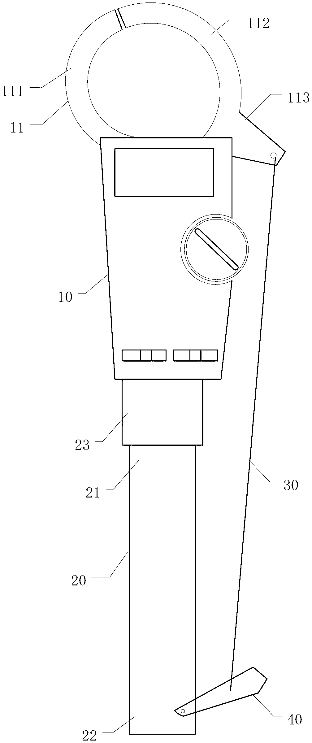
[0025] figure 1 It is a structural diagram of a current measuring device disclosed in the embodiment of this application.
[0026] Such as figure 1 The current measuring device shown includes a clamp meter 10 , a retractable insulating handle 20 , a coupling 23 , a pull wire 30 and a handle 40 . The clamp ammeter 10 is hinged to the upper end 21 of the insulating rod 20 through a coupling 23 , and the clip 113 of the clamp ammeter 10 for opening the clamp head 11 is connected to the handle 40 through a pull wire 30 .
[0027] Clamp ammeter 10 comprises pincer head 11, and pincer head comprises fixed bayonet 111 and movable bayonet 112, and when movable bayonet 112 moves, pincer head 11 will open, and now will open pincer head 11 block and wait for The wire measured, then close the clamp head 11, just can measure. The movable bayonet 112 is provided with a locking member 113 for moving the movable bayonet 112 to open the pliers 11 .
[0028] The insulating handle 20 is a ho...
Embodiment 2
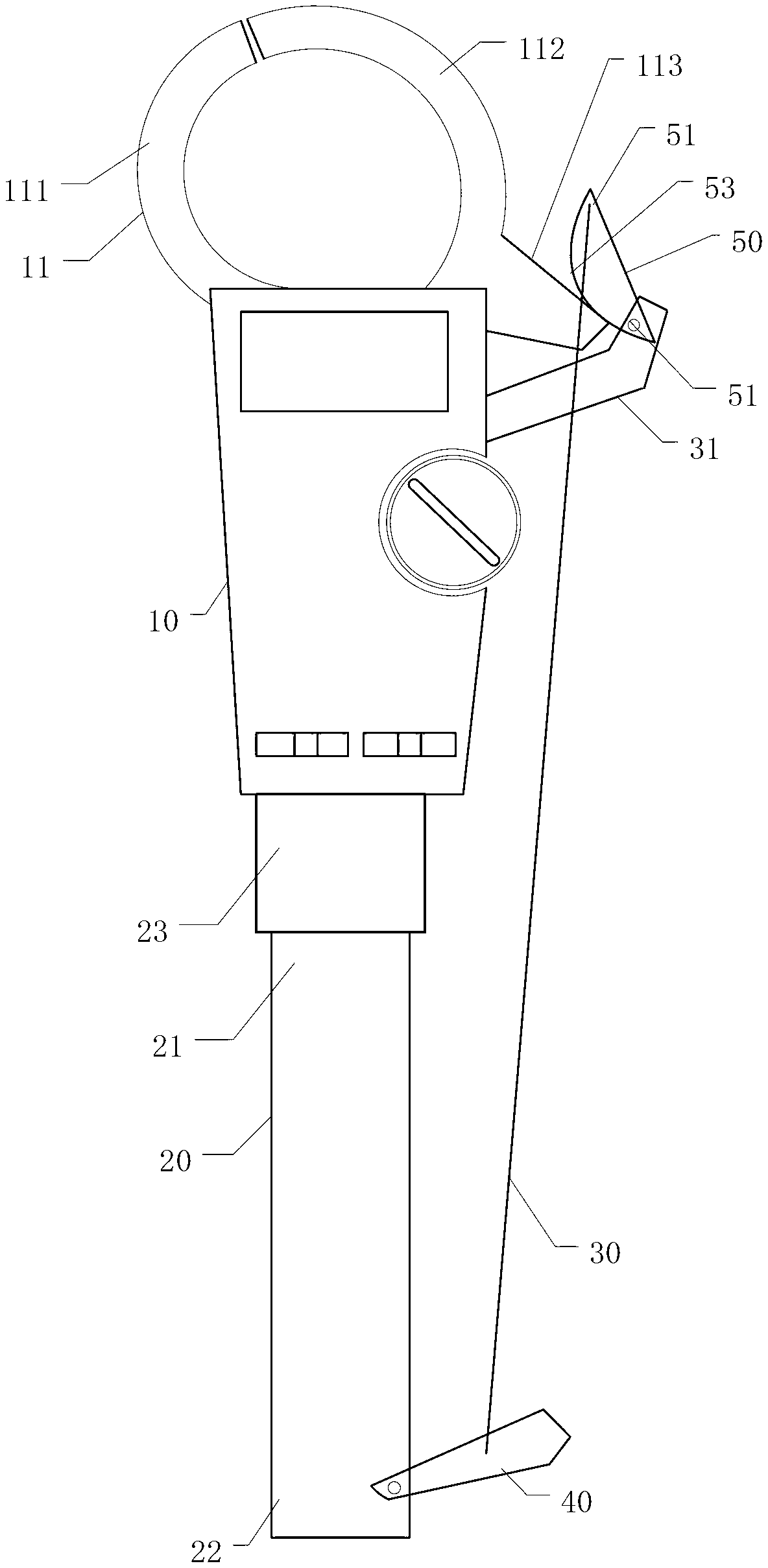
[0034] figure 2 It is a structural diagram of another current measuring device disclosed in the embodiment of the present application.
[0035] In the first embodiment, the clamp 113 is directly pulled by the pull wire 30 to move the movable bayonet 112 to complete the action of opening the pliers 11 . In this embodiment, a pressure plate 50 is added, and the clamp 113 is pushed by the pressure plate 50 to open the pliers head 11 .
[0036] Such as figure 2 As shown, a first support 31 is provided on the clamp body of the clamp ammeter 10, and one end of the first support 31 is fixedly connected with the body of the clamp ammeter 10, and the other end is provided with a pressing plate 50, and the fixed end 51 of the pressing plate 50 is connected to the clamp body of the clamp ammeter 10. The first bracket 31 is connected by a rotating shaft. The first bracket 31 can also be disposed on the insulating handle 20 .
[0037] The shape of the pressing plate 50 is preferably ...
Embodiment 3
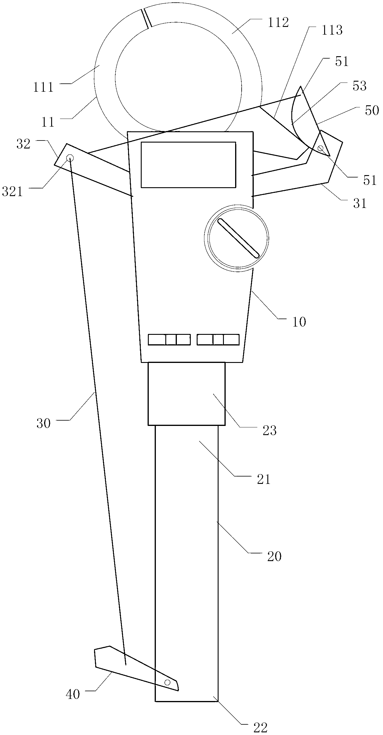
[0040] image 3 It is a structural diagram of another current measuring device disclosed in the embodiment of the present application.
[0041] In the second embodiment, when the angle between the ammeter clamp 10 and the insulating handle 20 is at a certain angle, pulling the pressing plate 50 may cause the pressing plate 50 to be far away from the clip 113 of the ammeter clamp 10, so that the pressing plate 50 cannot be aligned with the clip. 113 exerts pressure to open the clamp head 11. At this time, it is necessary to repeatedly adjust the angle of the clamp ammeter 10 and the insulating handle 20, which is inconvenient to use. To solve this problem, a guide hole 321 is added on the basis of the second embodiment.
[0042] Such as image 3 In the shown current measuring device, a second bracket 32 is provided on the side of the clamp-on ammeter 10 near the fixed bayonet 111 of the clamp head 11, and one end of the second bracket 32 is fixedly connected to the clamp-...
PUM
 Abstract
Description
Claims
Application Information