LLC resonant converter, controlling circuit and driving method thereof

A technology for controlling circuits and circuits, which is applied to conversion equipment with intermediate conversion to AC, conversion of AC power input to DC power output, and conversion of DC power input to DC power output, etc., which can solve problems such as bridge arm penetration

Active Publication Date: 2013-09-25
CHENGDU MONOLITHIC POWER SYST
View PDF3 Cites 14 Cited by
  • Summary
  • Abstract
  • Description
  • Claims
  • Application Information

AI Technical Summary

Problems solved by technology

In a working cycle, the two synchronous rectifiers on the secondary side of the transformer will be turned off or on repeatedly, and even the bridge arm will be cut through.

Method used


Image

  • LLC resonant converter, controlling circuit and driving method thereof
  • LLC resonant converter, controlling circuit and driving method thereof
  • LLC resonant converter, controlling circuit and driving method thereof

Examples


Embodiment Construction

[0024] Specific embodiments of the present disclosure will be described in detail below, and it should be noted that the embodiments described here are only for illustration, and are not intended to limit the present disclosure. On the contrary, the disclosure is intended to cover various alternatives, modifications and equivalents as defined within the spirit and scope of the disclosure as defined by the appended claims. In the following description, numerous specific details are set forth in order to provide a thorough understanding of the present disclosure. However, it will be understood by those of ordinary skill in the art that the present disclosure may be practiced without these specific details. In some other embodiments, well-known schemes, processes, components, circuits or methods are not described in detail in order to highlight the gist of the present disclosure.

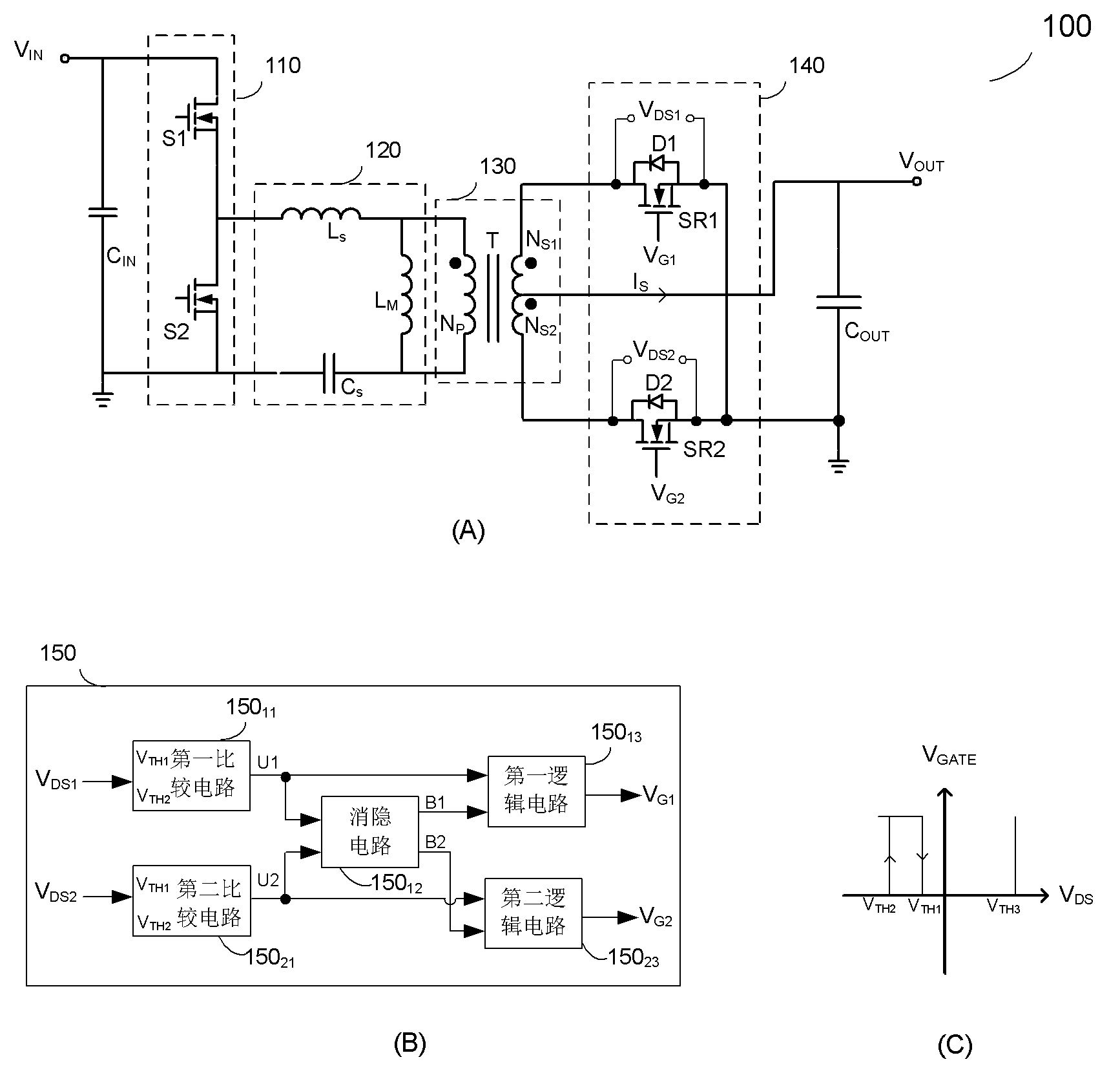
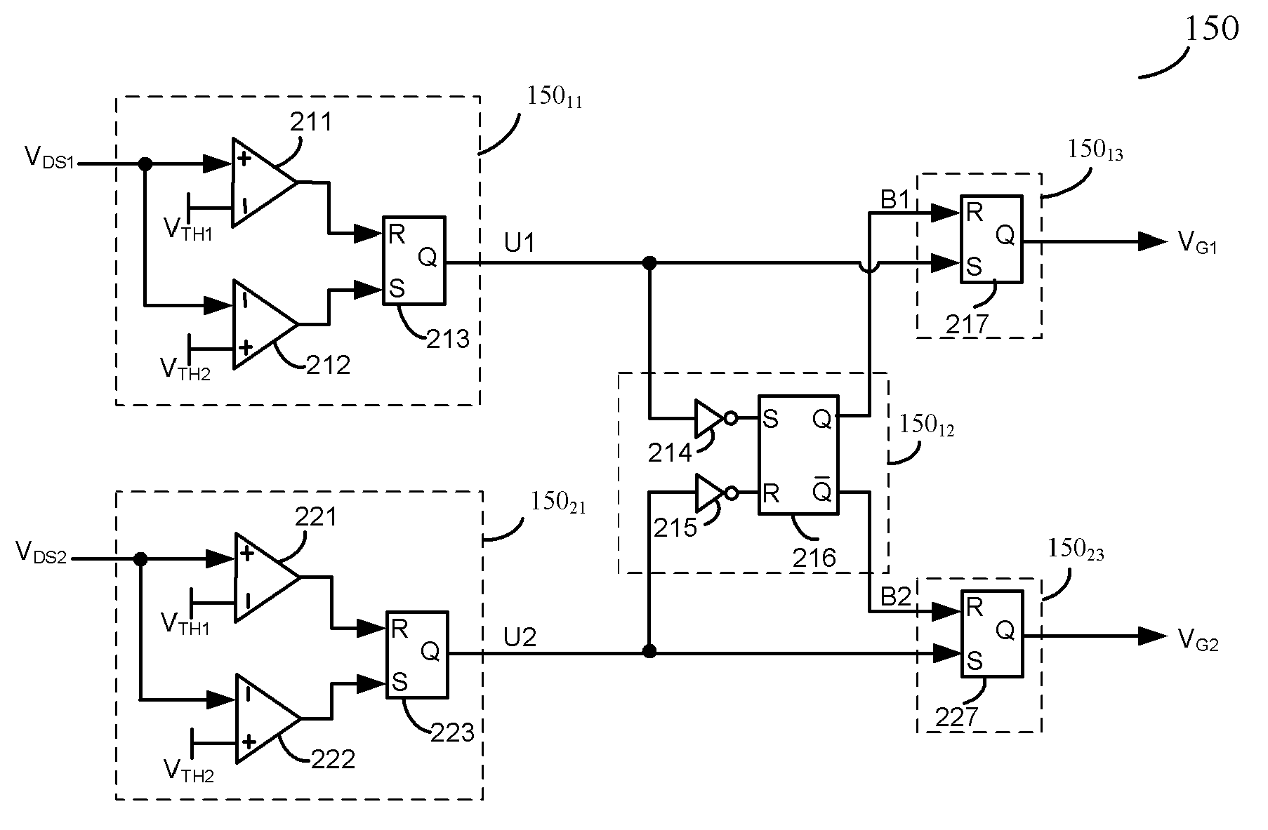
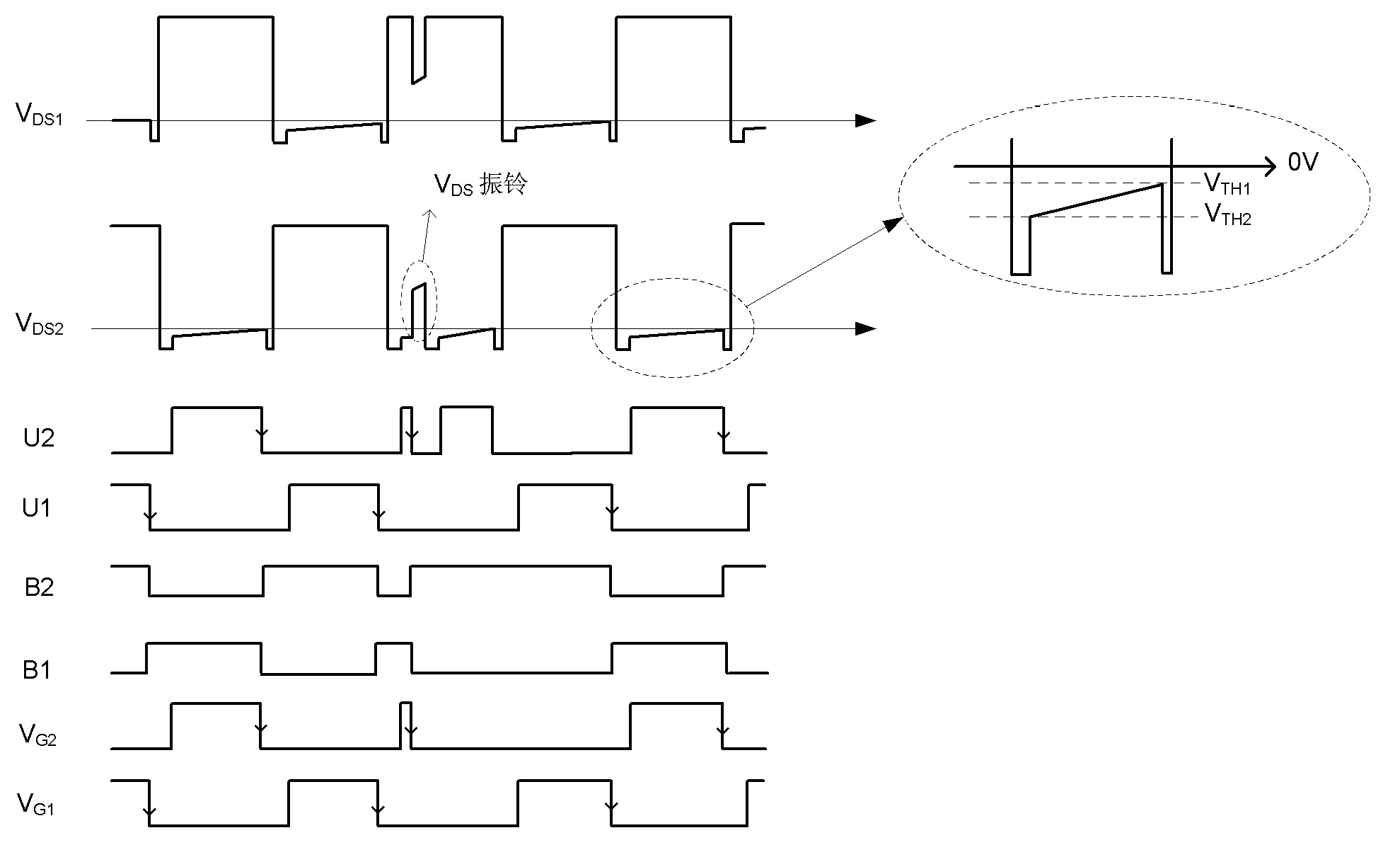
[0025] Based on the possible problems in the working process of the synchronous rectifier in the L...


PUM


Abstract

The invention discloses an LLC resonant converter, a controlling circuit of the LLC resonant converter, and a driving method of the LLC resonant converter. The bridge-type LLC resonant converter comprises a bridge-type circuit, a resonant network, a transformer, a synchronous rectifying circuit and the controlling circuit. The synchronous rectifying circuit at least comprises a first synchronous rectifying pipe and a second synchronous rectifying pipe. The controlling circuit comprises a first comparison circuit, a second comparison circuit, a blanking circuit, a first logic circuit and a second logic circuit. A first blanking signal and a second blanking signal are provided through the blanking circuit, and multiple times of conduction and turning-off of the first synchronous rectifying pipe and the second rectifying pipe in one cycle are avoided.

Description

technical field [0001] The disclosed embodiments of the present invention relate to an electronic circuit, in particular to an LLC resonant converter, a control circuit thereof, and a driving method for a synchronous rectification power switch tube. Background technique [0002] In many low-voltage, high-current applications, in order to reduce circuit losses, synchronous rectifiers are often used instead of ordinary diodes. However, during circuit operation, the synchronous rectifier is often disturbed by parasitic parameters or noise, which will cause it to be turned on or off repeatedly in one cycle. For example, in an LLC resonant circuit with synchronous rectification, once the synchronous rectifier is disturbed by parasitic parameters and rings, the normal turn-off and turn-on of the dual channels of the secondary side of the transformer will be interrupted. In one working cycle, the two synchronous rectifiers on the secondary side of the transformer will be repeatedl...

Claims


Application Information

Patent Timeline
Patent Type & Authority Applications(China)
IPC IPC(8): H02M3/28H02M1/00
CPCH02M3/33592H02M7/217Y02B70/10Y02P80/10H02M1/0058
Inventor 缪磊
Owner CHENGDU MONOLITHIC POWER SYST
Why Eureka
Try Eureka