
Wire harness protector

A technology of protectors and wire harnesses, applied in the direction of electrical components, circuits or fluid pipelines, connecting end caps, etc., can solve problems such as not easy to ensure, and achieve the effect of effectively accommodating and maintaining insulation reliability

Inactive Publication Date: 2013-09-25
SUMITOMO WIRING SYST LTD
View PDF6 Cites 9 Cited by
  • Summary
  • Abstract
  • Description
  • Claims
  • Application Information

AI Technical Summary

Problems solved by technology

Therefore, due to the increase and enlargement of the connectors, it is not easy to secure accommodating parts that can accommodate the connectors in a state that ensures insulation reliability.

Method used


Image

  • Wire harness protector
  • Wire harness protector
  • Wire harness protector

Examples


Embodiment Construction

[0042] Hereinafter, embodiment of the protector of this invention is demonstrated based on drawing.

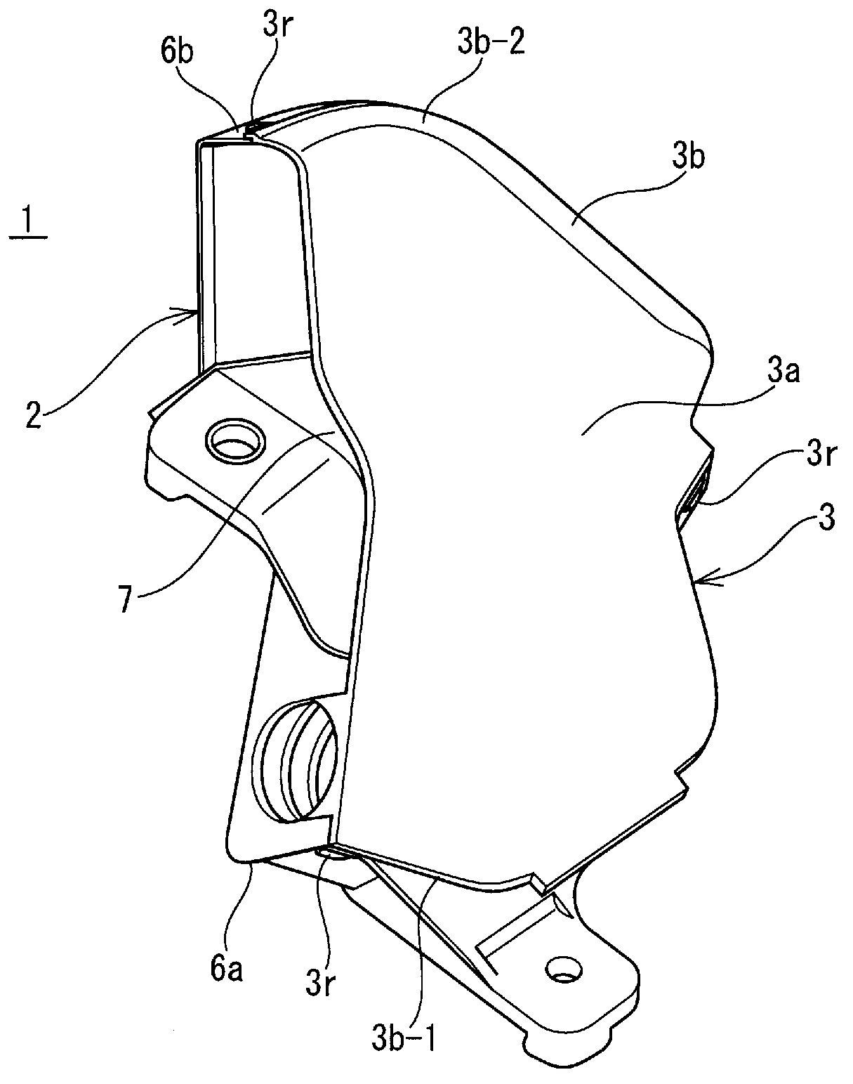
[0043] The protector 1 of the embodiment is a protector for a wire harness arranged in an automobile, and the protector 1 of the present embodiment is arranged in an engine room in a submerged area.

[0044] The protector 1 is composed of a main body 2 and a cover 3 covering an opening on the upper surface of the main body 2, and both the main body 2 and the cover 3 are resin molded products.

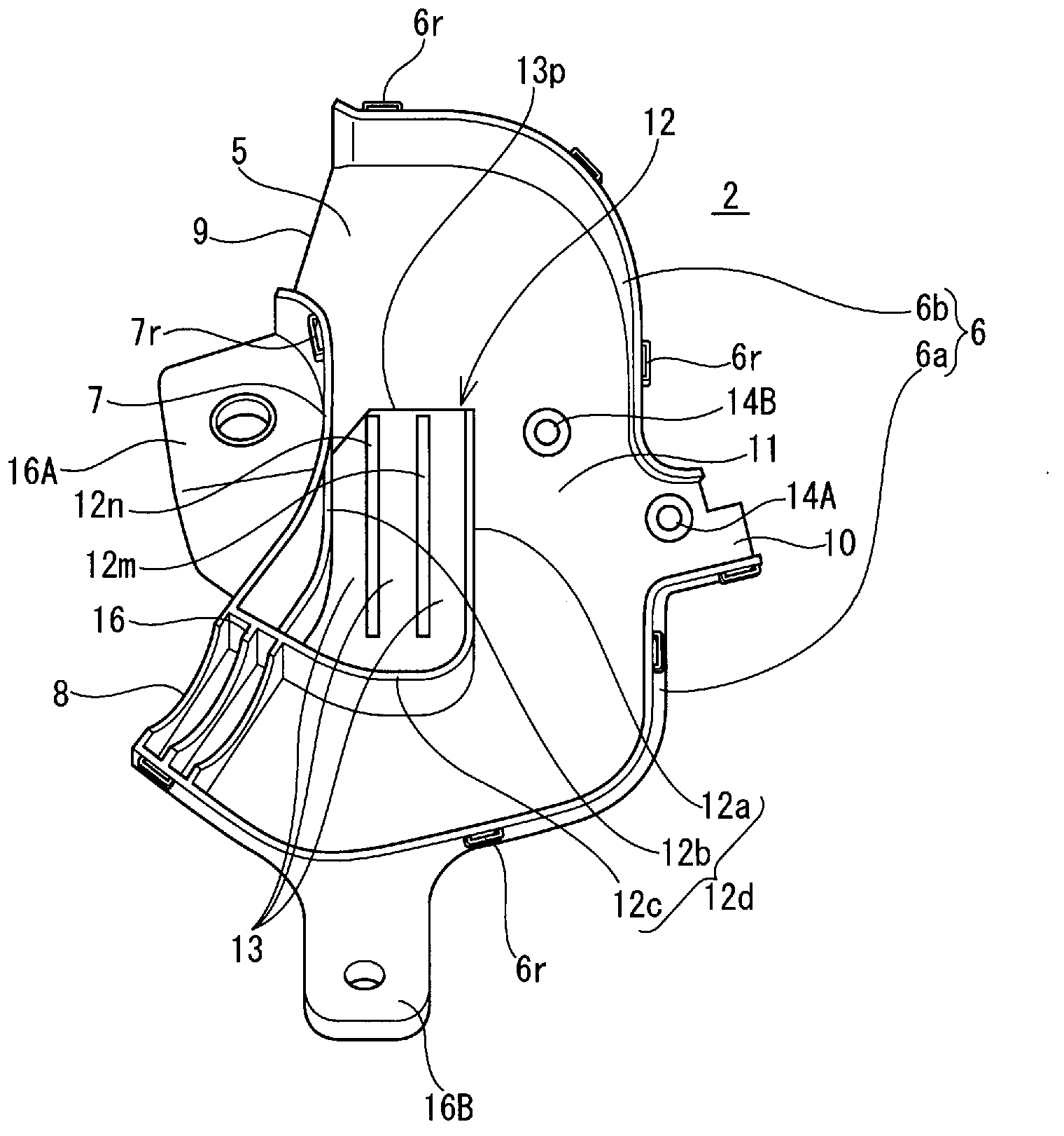
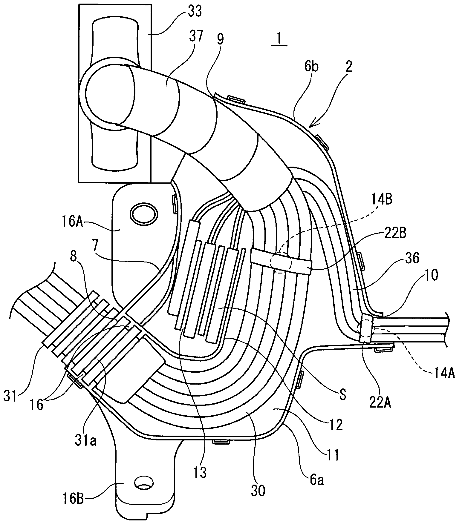
[0045] Such as figure 2, 3 As shown, the main body 2 has a bottom wall 5 and a peripheral wall composed of an outer side wall 6 and an inner side wall 7 protruding from both sides of the bottom wall 5 in the width direction. The outer wall 6 is bent in a substantially C shape with a large arc as a whole, and an inlet 8 and an outlet 9 for the harness opening in the same direction are provided between the inner wall 7 and both ends in the longitudinal direction of the outer wall 6 . ...


PUM


Abstract

The present invention enables many splices to be housed inside a protector provided on the outside of a wire harness. A splice housing part protrudes from a bottom wall into a side space of a main wire harness passage enclosed by the bottom wall and peripheral walls of the body of the protector. The splice housing part is provided with partition walls erected at regular intervals, and a blocking wall on one side of the partition walls. A plurality of splice chambers, which are sandwiched by the partition walls, are provided in a row, and the side facing the blocking wall of each splice chamber serves as an insertion opening. Each splice chamber: is set at a height that enables splices to be housed in at least two vertical tiers; and, among the splices that branch from the wire harness, houses, in a vertically adjacent manner, a splice wrapped with a splice sheet on the outer peripheral surface, and a splice covered with a cap made of an insulating resin.

Description

technical field [0001] The present invention relates to a protector for a wire harness, and in particular, it is possible to efficiently insulate and accommodate a plurality of joint portions provided in a wire harness in the protector. Background technique [0002] The wiring harness arranged in a vehicle is composed of a bundle of multiple wires. With the rapid increase of electronically controlled automotive components, the proportion of shielded wires among the wires constituting the wiring harness has increased. These shielding wires need to ground the shielding layer made of metal materials, and if the shielding wires are added, additional shielding connectors for connecting the shielding layer to the ground wire (drain wire) will increase. Since the wire harness connected to the large electronic control unit includes a plurality of shielded wires, the number of connectors branching from the wire harness is also multiplied and tends to be concentrated at the end portio...

Claims


Application Information

Patent Timeline
Patent Type & Authority Applications(China)
IPC IPC(8): H02G3/04B60R16/02H01R4/22
CPCB60R16/0215H02G3/04
Inventor 原一生
Owner SUMITOMO WIRING SYST LTD
Learn More