Gas-insulated switching device
A gas-insulated switch and gas technology, which is applied to the installation of switchgear with metal casing, electrical switches, electrical components, etc., can solve the problem of reducing the insulation resistance of insulating operating rods, hindering the miniaturization of switches, and reducing insulation resistance, etc. problem, to achieve the effect of excellent decomposition gas, reduced residual stress, and improved insulation resistance
- Summary
- Abstract
- Description
- Claims
- Application Information
AI Technical Summary
Problems solved by technology
Method used
Image
Examples
Embodiment 1
[0039] Embodiments of the present invention will be described below with reference to the accompanying drawings.
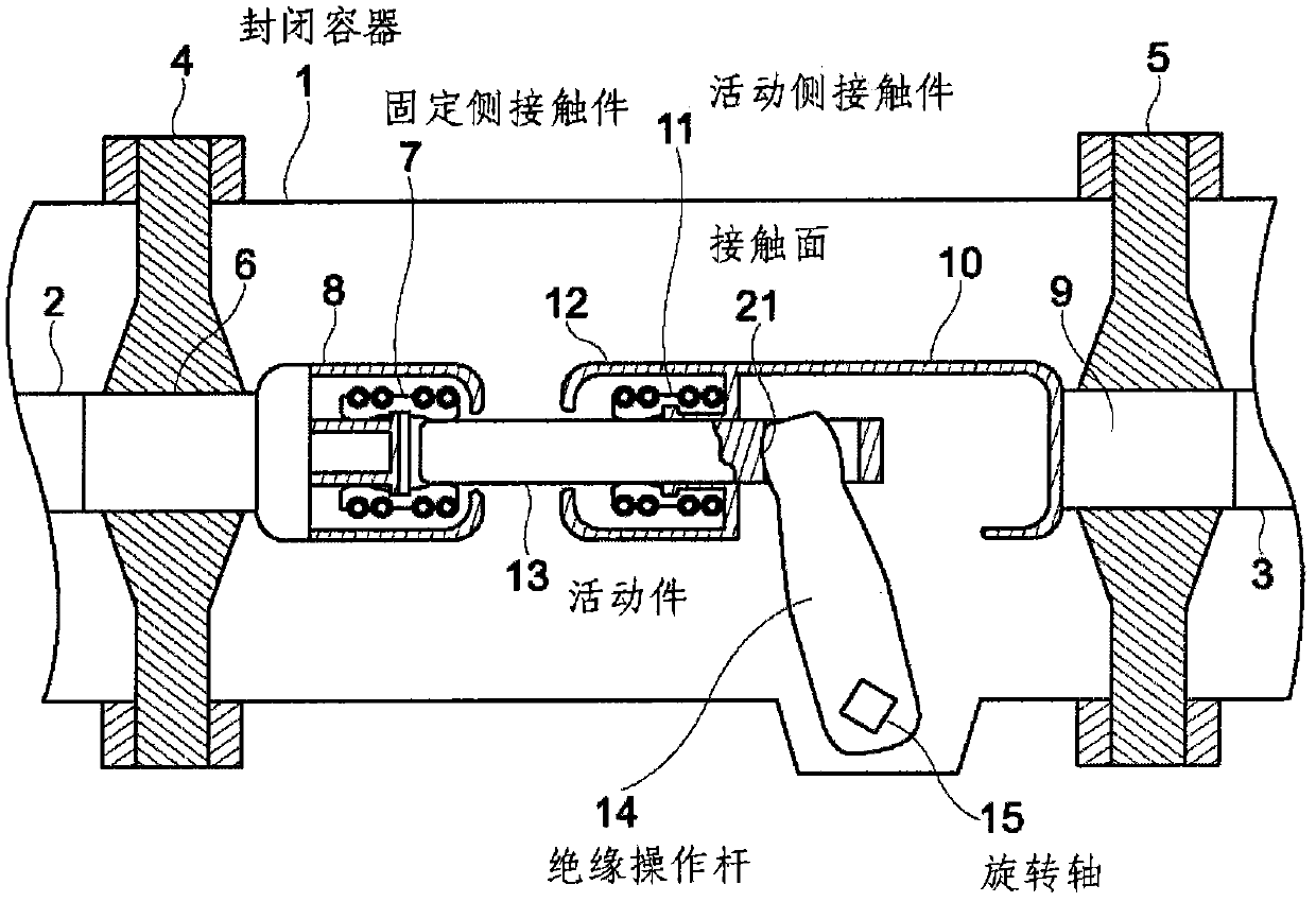
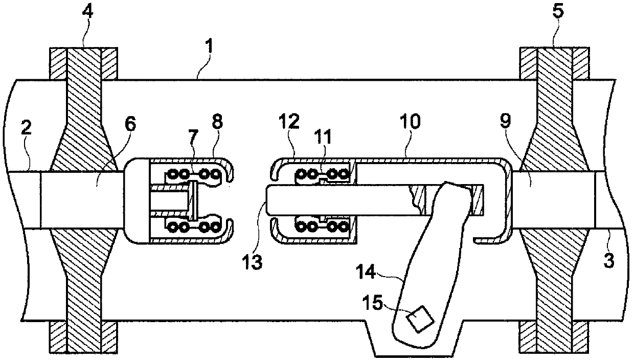
[0040] figure 1 It is a cross-sectional view of a circuit breaker as a gas insulated switchgear showing an embodiment of the present invention;
[0041] In the interior of the closed container 1 that is sealed with pressurized nitrogen, dry air, SF6 gas, etc., to achieve ground contact, in the state of electrical insulation from the sealed container 1 through the insulating spacers 4, 5, the support height Voltage conductors 2,3.
[0042] On the central conductor 6 of the insulating spacer 4 , a fixed-side contact 7 is attached, and a shield case 8 for electric field relaxation is provided on the outer peripheral portion of the fixed-side contact 7 . In addition, a movable side contact 11 is attached to the center conductor 9 of the insulating spacer 5 via a movable side cylindrical conductor 10 , and a shield case 12 for electric field relaxation is provided on...
Embodiment 2
[0094] Figure 15 and Figure 16 It is a plan view and a cross-sectional view of the contact connection structure between the insulating operating rod 14 and the movable part 13 of another embodiment.
[0095] The structure of the contact surface 21 on the free end side of the insulating operating rod 14 is the same as that in the above case. In addition, the movable member 13 has a holding portion 29 connected to the insulation operating rod 14 on the right, unlike the conductor portion on the left for conducting electricity. Hold section 29 has a pass Figure 13 The illustrated through hole 27 is detachably fixed to the conductor portion by means of a screw thread 30 .
[0096] because the elephant also according to Figure 11 As known from the relationship between the movable part 13 and the movable side contact 11, no current flows in the holding part 29 which is independent of the conductor part, so its constituent material can be either a metal material or an insulat...
Embodiment 3
[0100] Figure 17 and Figure 18 It is a plan view and a cross-sectional view showing the contact connection structure of the insulating operating rod 14 and the movable member 13 in another embodiment.
[0101] The example is with Figure 15 and Figure 16 In the same contact connection structure as shown, at the contact portion between the retaining portion 29 of the movable member 13 and the insulating operating rod 14, thin films 31a, 31b of solid lubricating material are provided. Fluorine resins such as polytetrafluoroethylene (PTFE) and the like can be used as the solid lubricant.
[0102] The entire holding portion 29 may be made of a solid lubricating material, but since it is difficult to ensure mechanical strength, it is most practical to provide the thin films 31a, 31b only at the contact portions as shown in the figure. Since the frictional force can be greatly reduced by the thin films 31a, 31b of the solid lubricant, the occurrence of foreign matter such as ...
PUM
 Abstract
Description
Claims
Application Information
 - R&D
- Intellectual Property
- Life Sciences
- Materials
- Tech Scout
- Unparalleled Data Quality
- Higher Quality Content
- 60% Fewer Hallucinations
Browse by: Latest US Patents, China's latest patents, Technical Efficacy Thesaurus, Application Domain, Technology Topic, Popular Technical Reports.
© 2025 PatSnap. All rights reserved.Legal|Privacy policy|Modern Slavery Act Transparency Statement|Sitemap|About US| Contact US: help@patsnap.com


