Method, device, and computer program for determining an offset angle in an electric machine

A technology of offset angle and voltage, which is applied in the direction of motor, motor control, AC motor control, etc.

Inactive Publication Date: 2013-09-25
ROBERT BOSCH GMBH
View PDF5 Cites 11 Cited by
  • Summary
  • Abstract
  • Description
  • Claims
  • Application Information

AI Technical Summary

Problems solved by technology

When installing the angle sensor, it cannot always be guaranteed that the angle sensor can be fixed in the desired position exactly with reference to the geometry of the motor
Therefore, there may be an angle α difference between the zero position of the angle sensor system set for the motor and the actual zero position of the motor

Method used


Image

  • Method, device, and computer program for determining an offset angle in an electric machine
  • Method, device, and computer program for determining an offset angle in an electric machine
  • Method, device, and computer program for determining an offset angle in an electric machine

Examples


Embodiment Construction

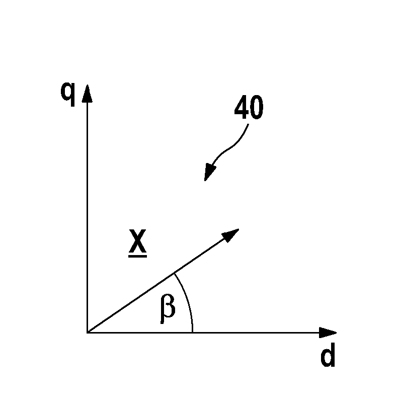
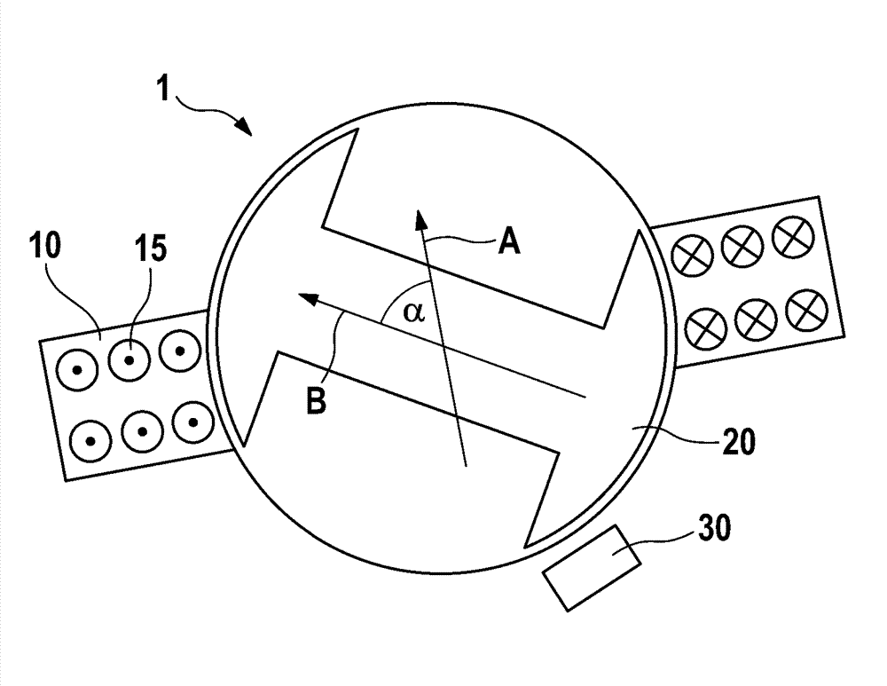
[0030] exist figure 1 An electrical machine 1 with a stator 10 having a stator winding 15 and a rotor 20 is shown in . The current flowing through the stator winding 15 exits the drawing in the winding section shown on the left and flows into the drawing in the winding section shown on the right. The resulting magnetic field has the direction of arrow A. For reasons of clarity, only a single stator winding 15 is shown, wherein usually the stator winding is arranged uniformly along the entire circumference of the stator. The rotor 20 is excited, for example by means of permanent magnets or a rotor winding (not shown), and has a magnetic field which is oriented in the longitudinal direction of the rotor, as indicated by arrow B. The force between the stator 10 and the rotor 20 is proportional to sin(α), where α is equal to the angle between the magnetic field A generated by the stator 10 and the magnetic field B generated by the rotor 20 .

[0031]The current orientation of r...


PUM


Abstract

The invention relates to a method and device for determining or checking the plausibility of an offset angle between an assumed orientation and an actual orientation of a rotor (20) relative to a stator (10) in an electric machine (1). In the method, the electric machine is first controlled in a quasi zero-current state, in which substantially no current should flow in the windings of the electric machine. Then a voltage indicator that specifies the direction of a voltage controlled in the electric machine during the quasi zero-current state is determined and subsequently transformed into a coordinate system that is fixed with respect to the rotor. The offset angle or an angle error with respect to a previously assumed, calibrated offset angle can be determined on the basis of the transformed voltage indicator.

Description

technical field [0001] The invention relates to a method for determining an offset angle in an electric machine. The invention furthermore relates to a device and a computer program designed to carry out the method according to the invention, as well as a computer-readable storage medium having a corresponding computer program stored thereon. Background technique [0002] Electric machines with high power potential are used, for example, in electric vehicles and hybrid vehicles. In this case, the electric machine can be operated in drive mode by acting as a motor, but also in generator mode by converting kinetic energy into electrical energy during the braking process. In this case, a torque can be transmitted from the electric machine to a shaft connected to the electric machine, again for example to the wheels of the vehicle. The torque here can assume a positive or negative value depending on whether the electric machine is operated in drive mode or in generator mode. ...

Claims


Application Information

Patent Timeline
Patent Type & Authority Applications(China)
IPC IPC(8): H02P25/02
CPCB60L15/025H02P2203/03H02P21/32Y02T10/64H02P6/18H02P25/02H02P6/182
Inventor K.舒斯特M.维尔特D.赖希勒G.格廷
Owner ROBERT BOSCH GMBH
Why Eureka
Try Eureka