
Variable-spacing picking and placing device

A pick-and-place device and variable pitch technology, applied in the direction of manufacturing tools, chucks, manipulators, etc., can solve the problems of low reliability of consistent action, easy aging of gas circuit components, high environmental requirements, etc., and achieve low cost and low occupation. Less space and less energy consumption

Active Publication Date: 2013-10-02
GOERTEK INC
View PDF7 Cites 2 Cited by
  • Summary
  • Abstract
  • Description
  • Claims
  • Application Information

AI Technical Summary

Problems solved by technology

[0002] At present, in many workpiece-intensive assembly occasions, it is often necessary to pick, place, load or unload parts at different intervals. The action requires accuracy, speed and high reliability. Multi-power devices are often used to realize the opening and closing and clamping actions respectively, and more The realization of pneumatic devices not only consumes high energy, but also has average efficiency, consistent action and low reliability, and the air circuit components are prone to aging, which is subject to high environmental requirements.

Method used


Image

  • Variable-spacing picking and placing device
  • Variable-spacing picking and placing device
  • Variable-spacing picking and placing device

Examples


Embodiment 1

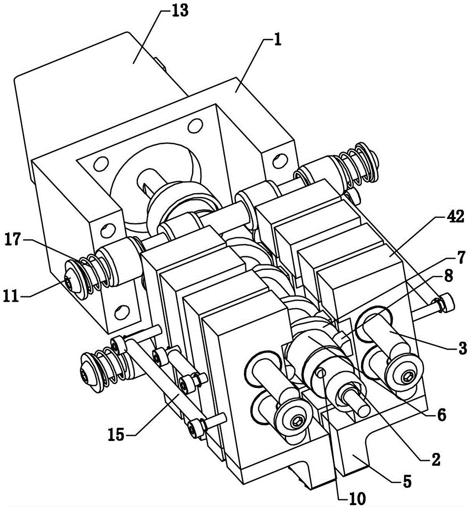
[0033] Such as figure 1 As shown, the variable-pitch pick-and-place device includes a frame 1. A camshaft 2 driven by a power device is rotatably installed on the frame 1, and two clamping jaw seat mounting shafts parallel to the camshaft 2 are provided on both sides of the camshaft 2 3. Each clamping jaw seat mounting shaft 3 is equipped with two clamping jaw seats 4, the clamping jaw seats 4 on the two clamping jaw seat mounting shafts 3 are arranged in pairs, and the pair of two clamping jaw seats 4 constitute a clamp Claw seat group, such as Figure 5 As shown, each clamping jaw base 4 is equipped with a clamping jaw unit 5, two clamping jaw units 5 on each clamping jaw base group constitute a pair of clamping jaws, and the camshaft 2 is fixedly installed for each A plate cam 6 that opens and closes between the two gripper seats 4 of a gripper seat group and an end cam 7 for separating and closing each gripper seat group and group along the axial direction of the camshaft, ...

Embodiment 2

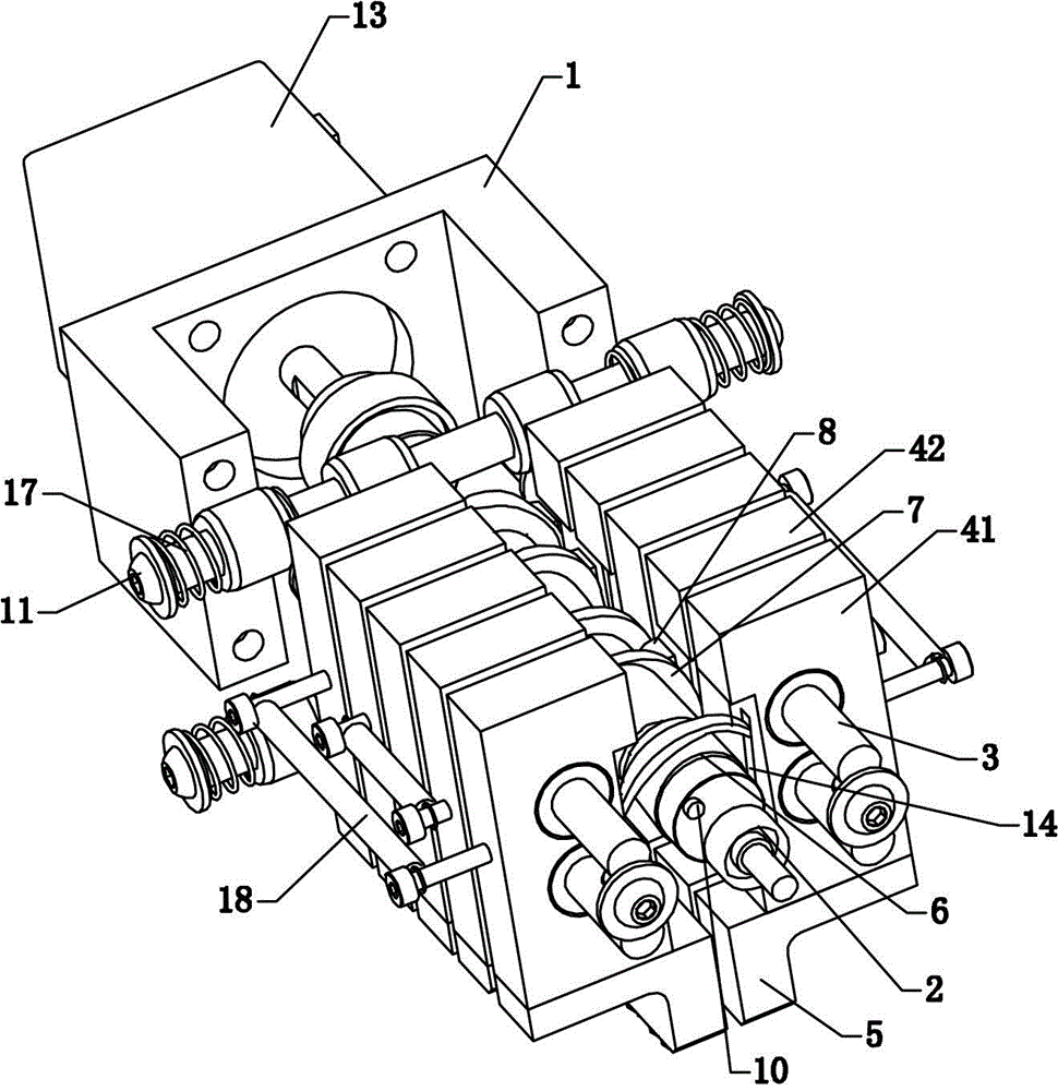
[0041] Such as figure 2 As shown, a variable-pitch pick-and-place device has basically the same structure as the first embodiment. The difference is that the clamping jaw holder group includes a fixed jaw holder group and a plurality of movable jaw holder groups, and several movable jaw holders The seat set is arranged on the same side of the fixed jaw seat set, and the fixed jaw seat set is limited along the axial direction of the camshaft 2. The fixed jaw seat 41 is provided with a limiting slot 14, and the plate cam 6 is restrained and installed in the limiting slot 14 Inside, an end face cam is provided between the two movable jaw seats 42 of each movable jaw seat group, and the two movable jaw seats 42 of each movable jaw seat group are provided with flanges that abut the end face cams In this embodiment, the fixed jaw seat 41 only opens and closes, and no displacement occurs in the axial direction. The movable jaw seat 42 opens and closes and also produces displacement in...

Embodiment 3

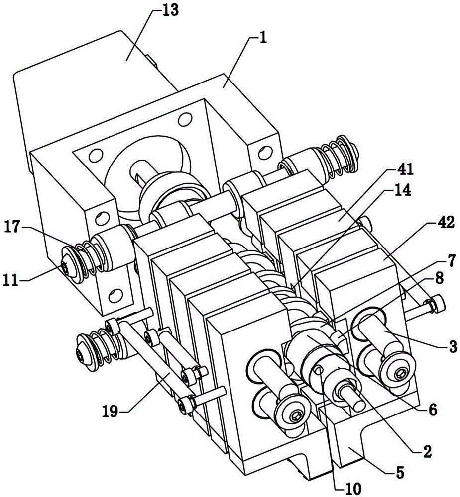
[0043] Such as image 3 , Figure 4 with Figure 5 Shown together, a variable pitch pick-and-place device, its structure is basically the same as the second embodiment, the difference is that as a preferred structure instead of sliding sleeve, the two clamping jaw seat mounting shafts 3 are respectively mounted on a sliding seat 16, at this time, the first reset mechanism is arranged between the two sliding seats 16, each sliding seat 16 is provided with a clamping jaw seat installation cavity, the clamping jaw seat mounting shaft 3 passes through the clamping jaw seat installation cavity, and the fixing clip The jaw seat 41 and several movable jaw seats 42 are installed in the installation cavity of the jaw seat. Based on the above structure, the first reset mechanism includes a spring limit post 11 installed on the frame 1, and two sliding seats 16 are slidably installed on the spring On the limit post 11, a second compression spring 17 is provided between each sliding seat 16...


PUM


Abstract

The invention discloses a variable-spacing picking and placing device. A camshaft is rotatably installed on a frame. Two clamping jaw seat installation shafts which are in parallel with the camshaft are arranged on the two sides of the camshaft. Camping jaw seats are installed on each clamping jaw seat installation shaft. The clamping jaw seats on the two clamping jaw seat installation shafts are arranged in a paired way. The two paired clamping jaw seats form a clamping jaw seat group. A plate cam which is used for enabling the two clamping jaw seats to be opened and closed and an end surface cam which is used for enabling the clamping jaw seat groups to increase or decrease the spacing along the axial direction of the camshaft are fixedly installed on the camshaft. A first restoring mechanism is arranged between the two clamping jaw seat installation shafts. The variable-spacing picking and placing device additionally comprises a second restoring mechanism which is matched with the end surface cam to realize the decrease of the spacing between the clamping jaw seat groups. The variable-spacing picking and placing device has the advantages that the spacing-increasing clamping action can be conveniently controlled by controlling the rotating speed of a motor, different picking and placing process requirements are realized, the production efficiency is improved, the structure is greatly simplified, the cost is low and the occupied space is small.

Description

Technical field [0001] The invention relates to a material clamping and taking equipment, in particular to a variable pitch taking and placing device. Background technique [0002] At present, in many workpiece-intensive assembly occasions, it is often necessary to pick and place parts or unload materials at intervals. The action requires accurate, fast and reliable action. Multi-power devices are often used to realize opening and closing and clamping actions respectively, and more The realization of pneumatic device not only consumes high energy, but also has average efficiency, consistent action and low reliability, and the components of the pneumatic circuit are prone to aging and are subject to higher environmental requirements. Summary of the invention [0003] The technical problem to be solved by the present invention is to provide a variable pitch pick-and-place device. By controlling the motor speed, it is convenient to control the pitch clamping action, realize different...

Claims


Application Information

Patent Timeline
Patent Type & Authority Applications(China)
IPC IPC(8): B25J15/08
Inventor 左春玉
Owner GOERTEK INC
Learn More