Conveying device

A technology of conveying device and conveying part, which is applied in the directions of conveyor, transportation and packaging, can solve the problems of large clamping force of the connecting cup, small application range, and the bottom of the connecting cup is easily scratched, etc., and achieves high working stability, Wide range of effects

Active Publication Date: 2013-10-02
HANGZHOU ZHONGYA MACHINERY CO LTD
View PDF9 Cites 11 Cited by
  • Summary
  • Abstract
  • Description
  • Claims
  • Application Information

AI Technical Summary

Problems solved by technology

[0004] When the case packer stops feeding the cups, the bottom of the cups and the load conveyor belt 22 are in a state of sliding friction connection, so the bottom of the cups is easily scratched during the cup feeding process; 23 and the load conveyor belt 22 are clamped, so there is a tight connection between the two conveyor belts and the connecting cup, so that the clamping force on the connecting cup is relatively large, and the cup body is squeezed, which is easy to make the cup body deformation
[0005] Since the distance between the cup feeding conveyor belt 23 and the loading conveyor belt 22 is constant, the conveyor device of this structure is only suitable for one size of connected cups, and has the disadvantage of a small application range.

Method used


Image

  • Conveying device
  • Conveying device
  • Conveying device

Examples


Embodiment Construction

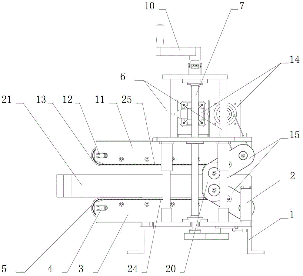
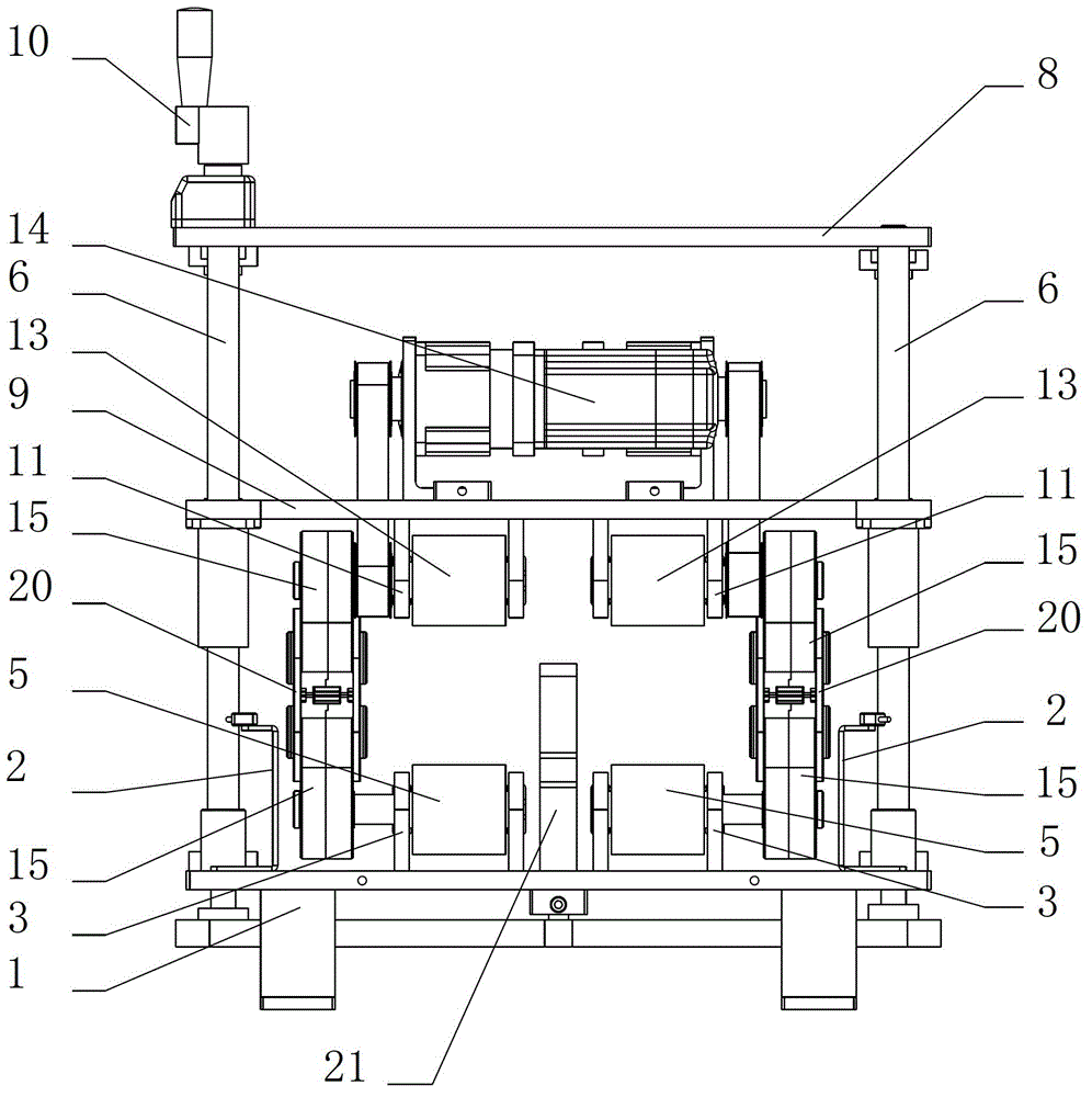
[0028] like figure 2 , 3 , 4, and 5, the conveying device includes a frame 1 and a clamping and conveying mechanism, and two clamping and conveying mechanisms are installed side by side on the frame 1. The clamping and conveying mechanism includes a conveying part I, a conveying part II, a transmission part, a power part 14 and a counting device 2 .

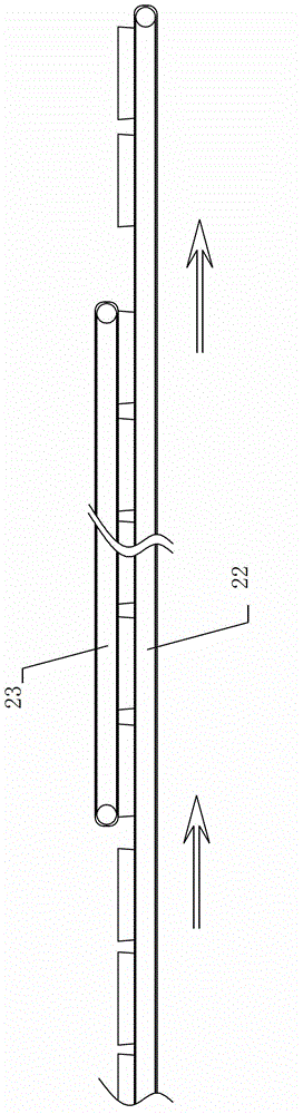
[0029] The conveying part I includes a bracket I3, a pulley I4, and a conveyor belt I5. The support I3 is fixedly connected to the frame 1, two pulleys I4 are installed on the support I3, and the conveyor belt I5 is installed on the two pulleys I4.

[0030] The frame 1 is provided with a lifting part, and the lifting part is located above the conveying part I. The lifting part includes a guide post 6, a screw mandrel 7, a top plate 8, and a mounting plate 9 for supporting and guiding. Four guide posts 6 distributed in a matrix are installed on the frame 1 , and the four guide posts 6 are in a parallel positional relationship...


PUM


Abstract

The invention discloses a conveying device. The conveying device comprises a rack and a clamping and conveying mechanism, wherein the clamping and conveying mechanism comprises a conveying part I, a conveying part II, a transmission part and a power part, the conveying part I is fixedly arranged on the rack, the conveying part II is movably connected to the rack through a lifting part, the conveying part I and the conveying part II are parallelly and oppositely arranged and are movably connected through the transmission part, and the power part is connected with the transmission part. The conveying device is provided with the clamping and conveying mechanism in synchronous reverse rotation with the same speed, the surfaces of goods and the conveying device are always in a stationary state when the goods are arranged at the inner part of the conveying device, and the goods can be prevented from suffering from sliding friction; the conveying device is provided with an independent power component, the conveying operation of the goods runs independently and cannot be affected by other devices, and the working stability is high; and the conveying device is enabled to be applied to goods conveying in various heights due to the regulation function of the clamping and conveying mechanism, and thus the conveying device also has the characteristic of wide application range.

Description

technical field [0001] The invention relates to a conveying device, in particular to a conveying device for conveying articles through a conveying belt. Background technique [0002] In packaging technology, wrapped cup-to-cup products, such as whole boxes of yogurt products, need to enter the packing station according to a certain cup feeding procedure before packing. After the continuous cups from the conveying device enter the packing station, they will go through the process of sorting operation at the packing station. In this process, the sorting equipment can only operate a certain number of continuous cups at a time, so the packing station must Cups are fed intermittently rather than continuously, otherwise the packing station cannot process all consecutive cups in time. [0003] The intermittent cup feeding process is controlled by a conveying device. In the prior art, the conveying device matched with the packing station includes a loading conveyor belt 22 and a cu...

Claims


Application Information

Patent Timeline
Patent Type & Authority Applications(China)
IPC IPC(8): B65G15/14
Inventor 史正姚辉
Owner HANGZHOU ZHONGYA MACHINERY CO LTD
Why Eureka
Try Eureka