Braking System

Inactive Publication Date: 2017-05-25
SAF HOLLAND GMBH
View PDF0 Cites 5 Cited by
  • Summary
  • Abstract
  • Description
  • Claims
  • Application Information

AI Technical Summary

Benefits of technology

[0005]In a preferred embodiment, the indicator unit can be fixed at least in sections to the carrier unit. The indicator unit is in this case particularly preferably an element such as for example a bolt which, by way of a corresponding engagement geometry, can be fixed in positively locking and/or non-positively locking fashion to the carrier unit. The indicator unit is in this case particularly preferably fixed to the carrier unit. It may furthermore be preferable for the indicator unit to be fixed cohesively to the carrier unit, for example by way of a welding process. As a result of the fixing of the indicator unit to the carrier unit, the exact position of the carrier unit relative to the reference geometry can be identified at all times by way of the indicator unit fixed to the carrier unit. In other words, the indicator unit does not move relative to the carrier unit.
[0006]It is furthermore preferable for the indicator unit to be guided at least in sections on the reference unit and to be secured against displacement transversely with respect to an indicator path. In addition or alternatively to the fixing of the indicator unit to the carrier unit, the indicator unit may also be guided on the reference unit. Here, it is merely necessary for the indicator unit to remain displaceable relative to the reference unit along an indicator path, because the position of the indicator unit on the indicator path relative to the reference unit must be variable in order to be able to indicate a particular state of wear of the brake system. The indicator path may in this case preferably be of straight or else slightly curved form. A straight form of the indicator path has the advantage that it is easy to produce. A curved indicator path advantageously follows the displacement movement of the carrier unit, which is preferably provided on the brake shoe, and thus permits exact determination of the position of the carrier unit, and thus an exact indication of the state of wear, with sliding friction being avoided. The indicator unit is preferably guided in a cutout of elongate form of the reference unit, which cutout extends substantially along the indicator path. In a particularly preferred embodiment, the indicator unit is guided on the reference unit and, here, is not fixed to the carrier unit. In this embodiment, when the brake system is actuated, the carrier unit abuts only against the indicator unit in order to displace the latter along the indicator path and move said indicator unit into a position relative to the reference unit which indicates a certain state of wear of the brake system. The indicator unit advantageously maintains the position of maximum deflection on the reference geometry even if the carrier unit has already been displaced backward by an actuation travel after the end of the actuation process of the brake system. It is advantageously possible for the state of maximum deflection to be read off as an indicator for the state of wear of the brake system even when the brake is not actuated.
[0007]It is furthermore preferable for the indicator unit to be displaceable in substantially translational fashion along the indicator path. Here, “substantially translational” means that relatively small deviations from the pure path movement without rotational components, which deviations do not exceed 10 percent of the main path movement, are possible within the scope of the invention. Here, the indicator path runs in the direction in which the carrier unit moves relative to the reference unit. In this way, it is possible to avoid cumbersome constructions with rotary axles and lever elements, so as not only to save weight but also keep the construction as simple as possible. It is advantageously possible to avoid transformations of movement directions, which give rise to increased susceptibility to faults and are liable to a relatively high level of wear of the components that are moved relative to one another.
[0008]In a further preferred embodiment, the indicator unit has an indicator element whose position relative to the reference geometry can be haptically and/or visually identified by a user. The indicator element is in this case preferably a section of the indicator element, or of one of several elements of the indicator unit, which is in particular designed for ass

Problems solved by technology

The brake systems known from the prior art are generally subject to usage-dependent wear, wherein, when the wear limit is reached, the braking action of the brake is diminished and is no longer ensured, and thus the driving safety of the utility vehic

Method used


Image

  • Braking System
  • Braking System
  • Braking System

Examples


Example

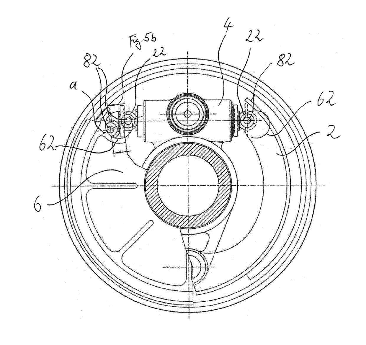
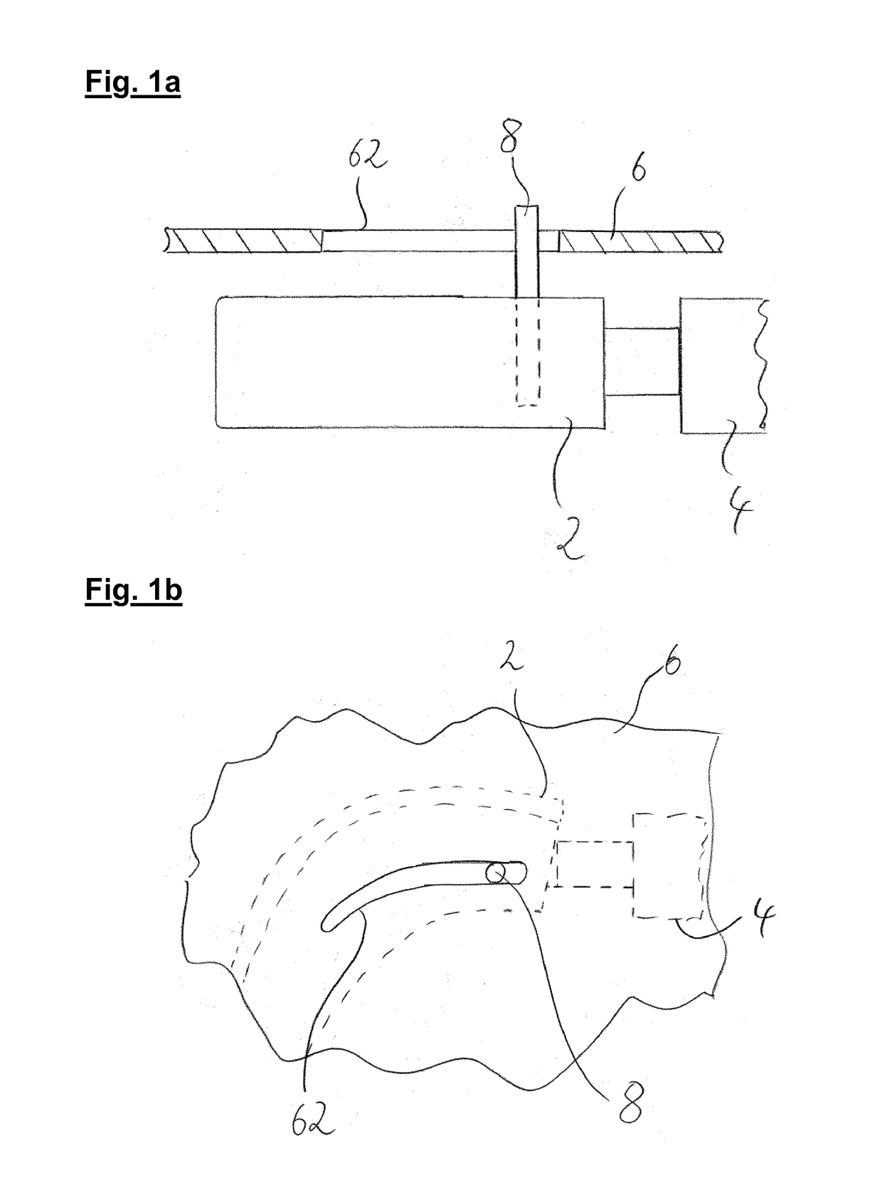
[0024]FIG. 1a shows, schematically and in greatly simplified form, the major components of the brake system according to the invention. Here, a carrier unit 2 is provided to which an indicator unit 8 is preferably fixed. Furthermore, an actuation unit 4 is provided which transmits a force to the carrier unit 2, which is preferably in the form of a brake shoe, in order to displace said carrier unit in the leftward direction in relation to the arrangement in the figure. Arranged above the carrier unit 2 and actuation unit 4 is a reference unit 6 which at least regionally covers or shields the carrier unit 2 and the actuation unit 4. In a particularly preferred embodiment, the reference unit 6 shields carrier unit 2 and actuation unit 4 completely in one direction, that is to say in the present example with respect to environmental influences from above. The reference unit 6 has a reference geometry 62 through which the indicator unit 8 advantageously projects at least in regions. In t...


PUM


Abstract

The invention relates to a brake system in particular for wedge-actuated drum brakes, comprising a carrier unit, an actuation unit, a reference unit and an indicator unit, wherein the reference unit shields the carrier unit and the actuation unit at least in regions, wherein the actuation unit engages on the carrier unit and displaces the carrier unit into a particular position relative to the reference unit or secures the carrier unit in one position relative to the reference unit, wherein the carrier unit engages on the indicator unit in order to displace the indicator unit into a particular position relative to the reference unit, wherein a state of wear of the brake system can be determined from outside the brake system by way of the position of the indicator unit relative to a reference geometry provided on the reference unit.

Description

BACKGROUND OF THE INVENTION[0001]The present invention relates to a brake system, in particular a wedge-actuated drum brake for use in utility vehicles.[0002]The brake systems known from the prior art are generally subject to usage-dependent wear, wherein, when the wear limit is reached, the braking action of the brake is diminished and is no longer ensured, and thus the driving safety of the utility vehicle can no longer be ensured. To be able to ensure the required safety, it has proven expedient here to provide wear displays or wear indicators on a brake system, by way of which the state of wear of the brake can be identified. In particular in the case of drum brakes, in which the wearing parts are arranged within the brake drum and are thus not visible to a user from the outside, it has hitherto been necessary here to resort to electrical wear indicators, which are for example integrated into the friction lining of the brake shoe and which, via a line system, transmit the state ...

Claims


Application Information

Patent Timeline
IPC IPC(8): F16D66/02F16D51/20
CPCF16D51/20F16D66/02F16D66/028
Inventor DREWES, OLAFMARSCHNER, OLIVER
Owner SAF HOLLAND GMBH
Why Eureka
Try Eureka