High flow traffic control system
A traffic control, high-flow technology, applied in traffic control system, traffic control system of road vehicles, control of traffic signals, etc., can solve the problem that the width of level crossing is not fully utilized, the signal control method is unreasonable, and the vehicle efficiency is low. and other problems, to achieve the effect of reducing traffic accidents and congestion, solving road congestion, and reducing the incidence.
- Summary
- Abstract
- Description
- Claims
- Application Information
AI Technical Summary
Problems solved by technology
Method used
Image

Examples
Embodiment 2
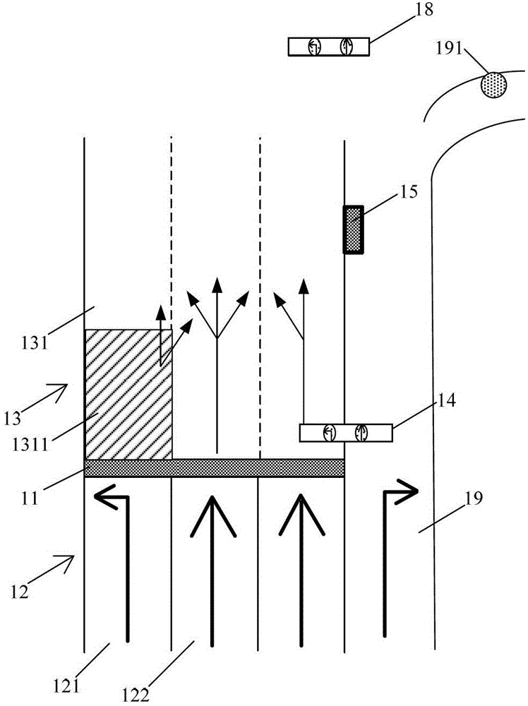
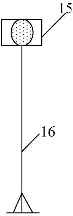
[0054] On the basis of embodiment one, traffic status indicator light 15 is set to a plurality of, and wherein the meaning of this multiple is more than 3, the traffic status that this traffic status indicator light 15 indicates and the traffic signal light device 14 that show. state, a number of traffic status indicator lights 15 periodically display corresponding image signals for controlling the speed of motor vehicles in the transition area 13; wherein, the traffic status indicator lights 15 can be arranged in the transition area 13 The position on the right side of , of course, can also be set in other spatial positions, which is not used to limit the present invention.
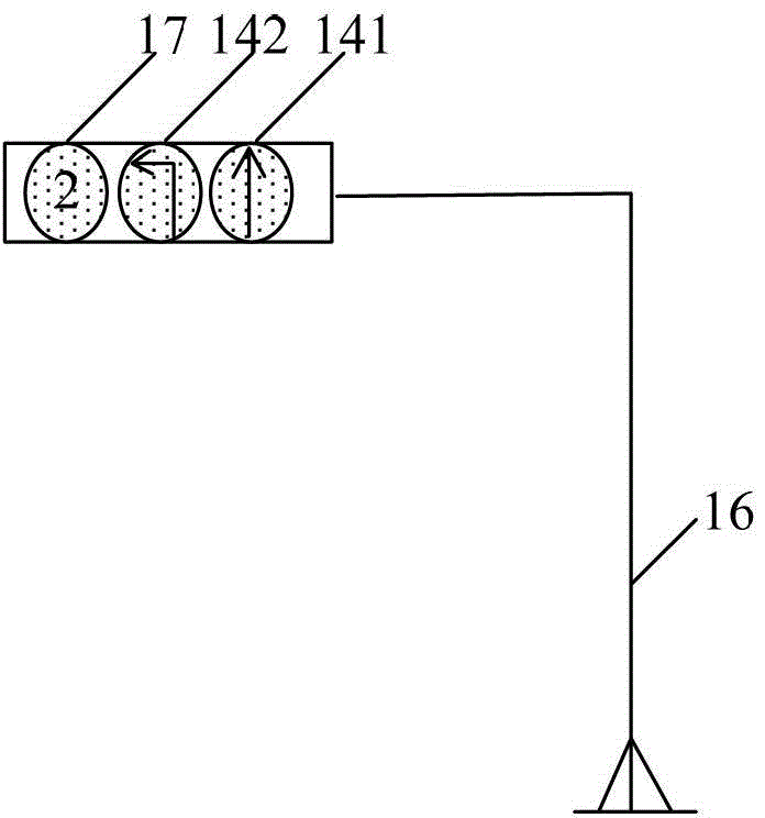
[0055] Among them, the image signal includes one or more of warning information, countdown information and traffic direction information, wherein the warning information includes three colors of red, yellow and green, the countdown information is the more common countdown number at present, and the traffi...
Embodiment 3
[0068] see Figure 4 , on the basis of Embodiment 1 or Embodiment 2, there is one passing state indicator light 15, and a stop waiting line 20 is provided at the lateral position of the transition area 13 corresponding to the passing state indicating light 15, and the stop waiting line 20 will The transition area 13 is horizontally divided into a plurality of waiting areas 131 for passing, and each waiting area 131 corresponds to a motor vehicle in a traffic direction of a signal light.
[0069] Among them, as shown in the figure, the stop waiting line 20 sets the transition area 13 as two passing waiting areas 131A and 131B. For the convenience of explanation, it is assumed that the first passing waiting area 131A buffers straight-going vehicles, and the second passing waiting area 131B buffers left-turning vehicles. vehicle;
[0070] When the straight running indicator light 141 of the traffic signal indicator light device 14 turned green, the vehicles waiting in the straig...
Embodiment 4
[0077] see Figure 5 , on the basis of Embodiment 1 or Embodiment 2, there are two traffic state indicator lights 15, and two stop waiting lines 20 are provided at the lateral position of the transition area 13 corresponding to the traffic state indicator lights 15, and the stop waiting lines 20 divides the transition area 13 horizontally into a plurality of waiting areas 131 for passing, and each waiting area 131 corresponds to a motor vehicle in a traffic direction of a signal light.
PUM
 Abstract
Description
Claims
Application Information
 - R&D
- Intellectual Property
- Life Sciences
- Materials
- Tech Scout
- Unparalleled Data Quality
- Higher Quality Content
- 60% Fewer Hallucinations
Browse by: Latest US Patents, China's latest patents, Technical Efficacy Thesaurus, Application Domain, Technology Topic, Popular Technical Reports.
© 2025 PatSnap. All rights reserved.Legal|Privacy policy|Modern Slavery Act Transparency Statement|Sitemap|About US| Contact US: help@patsnap.com