
Radially and axially integrated sliding bearing

A technology for sliding bearings and radial shafts, applied in sliding contact bearings, shafts and bearings, bearings for rotating motion, etc., can solve the problems of non-standard, complex structure, high heat generation, etc., and achieve compact structure and insensitivity to thermal expansion Effect

Inactive Publication Date: 2013-10-02
SHANGHAI UNIV
View PDF5 Cites 11 Cited by
  • Summary
  • Abstract
  • Description
  • Claims
  • Application Information

AI Technical Summary

Problems solved by technology

[0003] However, sliding bearings also have disadvantages such as high heat generation, non-standard, complex structure, and large volume. Under high speed conditions, heat generation is the main factor affecting the performance of sliding bearings.

Method used


Image

  • Radially and axially integrated sliding bearing
  • Radially and axially integrated sliding bearing
  • Radially and axially integrated sliding bearing

Examples


Embodiment 1

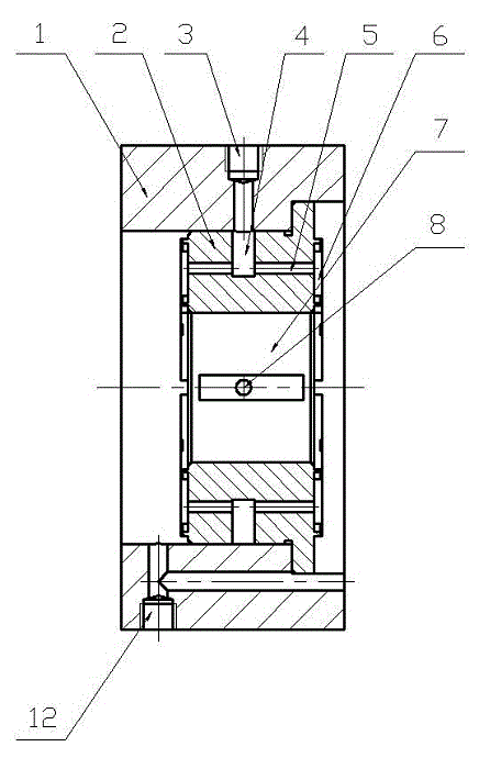
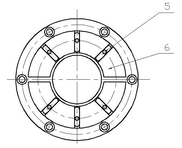
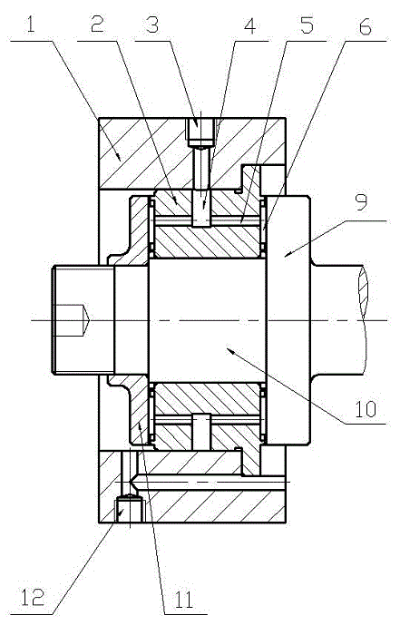
[0020] see Figure 1~Figure 3 , the radial and axial integrated sliding bearing, which includes a bearing seat 1, a bearing bush 2, a shaft 10 with a shoulder 9 and a retaining ring 11. It is characterized in that the bearing pad 2 is integrated with a radial bearing pad 7 and two thrust bearing pads 6, and the bearing pad 2 is provided with a circumferential oil inlet groove 4, a thrust bearing oil inlet hole 5 and a radial bearing oil inlet hole 8 connected to each other. The radial bearing bush 7 and the thrust bearing bush 6 have an oil inlet hole 3 connected to the circumferential oil inlet groove 4 of the bearing bush 2 on the bearing housing 1, and an oil outlet hole 12 on the bearing housing 1 communicates with the cavities at both ends of the bearing 2. During operation, the lubricating oil enters the circumferential oil inlet groove 4 through the oil inlet hole 3, and then a part of the lubricating oil enters the gap between the rotating shaft 10 and the radial beari...

Embodiment 2

[0022] see figure 1 and image 3 , this embodiment includes bearing seat 1, bearing bush 2, oil inlet hole 3, circumferential oil inlet groove 4, thrust bearing oil inlet hole 5, thrust bearing bush 6, radial bearing bush 7, radial bearing oil inlet hole 8, shaft shoulder 9, rotating shaft 10. Back-up ring 11 and oil outlet hole 12.

[0023] The bearing bush 2 is fixed to the bearing seat 1 by bolts, and the retaining ring 11 is connected with the rotating shaft 10 . When working, the rotating shaft 10 rotates, driving the retaining ring 11 to rotate, the lubricating oil enters the circumferential oil inlet groove 4 through the oil inlet hole 3, and part of the lubricating oil enters the gap between the rotating shaft 10 and the radial bearing bush 7 through the oil inlet hole 8 of the radial bearing. Under the rotation of 10, an oil film is formed to bear the radial load, after which, the lubricating oil leaks out from the gap and flows out from the oil outlet 12.

[0024]...


PUM


Abstract

The invention relates to a radially and axially integrated sliding bearing. The sliding bearing comprises a bearing pedestal, a bearing shell, an oil inlet port, a circumferential oil inlet groove, a thrust bearing oil inlet port, a thrust bearing shell, a radial bearing shell, a radial bearing oil inlet port, a bearing shoulder, a rotating shaft, a back-up ring and an oil outlet port. When the bearing is running, lubricating oil is injected into the circumferential oil inlet groove of the bearing shell through the oil inlet port; then part of the lubricating oil enters into a gap between the rotating shaft and the radial bearing shell through the radial bearing oil inlet port, and an oil membrane is formed as the rotating shaft rotates, and the oil membrane is used for bearing radial load; meanwhile, another part of the lubricating oil enters into a gap among the thrust bearing shell, the bearing shoulder and the back-up ring through the thrust bearing oil inlet port, and an oil membrane is formed as the bearing shell and the back-up ring rotate, and the oil membrane is used for bearing bidirectional axial load. The radially and axially integrated sliding bearing is capable of bearing both radial load and bidirectional axial load.

Description

technical field [0001] The invention relates to a radial and axial integrated sliding bearing in the mechanical field. Background technique [0002] According to the different friction properties in bearings, bearings are divided into two categories: sliding bearings and rolling bearings. Rolling bearings are widely used in general machines because of their small friction coefficient and low starting resistance, and they are standardized, easy to select, lubricate, and maintain. However, as machines are increasingly developing towards high speed and high power, the unique advantages of the sliding bearing itself, such as non-contact, large load capacity, and long life, make it also occupy an important position in modern machinery. [0003] However, sliding bearings also have disadvantages such as high heat generation, non-standard, complex structure, and large volume. Under high-speed conditions, heat generation is the main factor affecting the performance of sliding be...

Claims


Application Information

Patent Timeline
IPC IPC(8): F16C17/10
Inventor 鲁豫鑫李松生俞锋
Owner SHANGHAI UNIV
Learn More