
Pneumatic accelerator for electro-pneumatic valve positioner

A valve positioner and accelerator technology, applied to valve details, valve devices, engine components, etc., can solve the problems that the electric valve positioner cannot work normally, cannot drive other components, and is unstable

Inactive Publication Date: 2013-10-02
CHANGSHU HUIER GASOLINEEUM & CHEM INDAL INSTR
View PDF4 Cites 0 Cited by
  • Summary
  • Abstract
  • Description
  • Claims
  • Application Information

AI Technical Summary

Problems solved by technology

However, the output air pressure signal of the electric valve positioner may be unstable due to long-distance transmission, and even the pressure is so low that it cannot drive other components, resulting in the electric valve positioner not working properly.

Method used


Image

  • Pneumatic accelerator for electro-pneumatic valve positioner

Examples


Embodiment Construction

[0011] The specific implementation manners of the present invention will be further described below in conjunction with the drawings and examples. The following examples are only used to illustrate the technical solution of the present invention more clearly, but not to limit the protection scope of the present invention.

[0012] The technical scheme of concrete implementation of the present invention is:

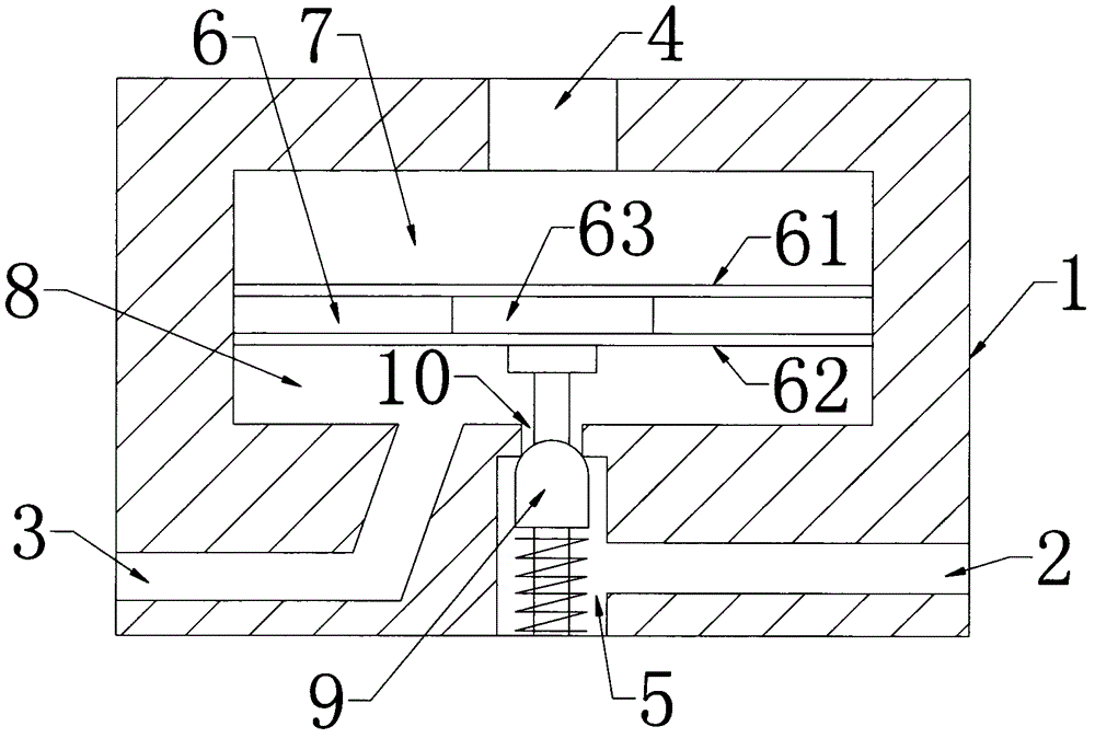
[0013] Such as figure 1 As shown, a pneumatic accelerator for an electric valve positioner includes a valve body 1. The valve body 1 is provided with an air source input end 2, a signal output end 3, a signal input end 4, and an air source chamber 5; the valve body 1 passes through a membrane assembly 6 Separate the input air chamber 7 and the feedback air chamber 8 arranged up and down; the membrane assembly 6 includes an upper diaphragm 61 and a lower diaphragm 62; the lower diaphragm 62 is connected to the valve core 9, and the valve core 9 runs through the air source ...


PUM


Abstract

The invention discloses a pneumatic accelerator for an electro-pneumatic valve positioner. The pneumatic accelerator comprises a valve body, wherein the valve body is provided with a gas source input terminal, a signal output terminal, a signal input terminal and a gas source bin; the valve body is divided into an input gas chamber and a feedback gas chamber, which are arranged up and down, through membrane components; the membrane components comprise an upper membrane and a lower membrane; the lower membrane is connected with a valve core penetrating the gas source bin; a gas source passage between the gas source bin and the feedback gas chamber is opened and closed through the valve core; the gas source input terminal is communicated with the gas source bin; the signal output terminal is communicated with the feedback gas chamber; the signal input terminal is communicated with the input gas chamber. The pneumatic accelerator for the electro-pneumatic valve positioner can effectively pressurize signal air pressure output by the electro-pneumatic valve positioner to enable the signal air pressure to meet the design requirements.

Description

technical field [0001] The invention relates to a pneumatic accelerator for an electric valve positioner. Background technique [0002] The electric valve positioner is the main accessory of the regulating valve. It is usually used in conjunction with the pneumatic regulating valve. It receives the output signal of the regulator, and then uses its output signal to control the pneumatic regulating valve. When the regulating valve operates, the displacement of the valve stem will Feedback to the valve positioner through the mechanical device, and the valve position status is transmitted to the upper system through the electrical signal. However, the output air pressure signal of the electric valve positioner may be unstable due to long-distance transmission, and even the pressure is so low that it cannot drive other components, resulting in the electric valve positioner not working properly. Contents of the invention [0003] The purpose of the present invention is to provi...

Claims


Application Information

Patent Timeline
Patent Type & Authority Applications(China)
IPC IPC(8): F16K31/02F16K31/126
Inventor 徐卫东徐志龙钱志航
Owner CHANGSHU HUIER GASOLINEEUM & CHEM INDAL INSTR
Learn More