Vacuum on-load tap changer

A technology of on-load tapping and vacuum, which is applied in the direction of transformers, electrical components, variable inductors, etc., can solve the problems of reduced rigidity of insulating blocks, large impact of fixed contacts, and large vibration, so as to reduce gear costs and reduce Sports impact, good effect of self-locking function

Active Publication Date: 2013-10-02
GUANGZHOU DEPOSON ELECTRIC TECH
View PDF8 Cites 2 Cited by
  • Summary
  • Abstract
  • Description
  • Claims
  • Application Information

AI Technical Summary

Problems solved by technology

This structure has the following disadvantages: (1) Since three slots are opened in the middle of the insulating block, the rigidity of the insulating block is reduced and the deformation is large
(2) There is a large gap between the roller bearing and the groove of the profiling plate. During the lifting process of the vacuum bubble, the profiling plate is pulled down by force, the carriage tilts, and the stroke of the vacuum bubble changes greatly. The vacuum bubble works low precision
(3) In this patent, the insulating shaft is installed in the middle of the frame, spanning the three-phase copper conductive rods, and the insulating beam is very close to the insulating shaft. When the air is humid and the insulating shaft is wet, creepage is very likely to occur on the surface of the insulating shaft, which may cause Insulator breakdown, causing accident
(4) In this patent, the second drive shaft derived from the only drive source is used to drive the accumulator, but because the second drive shaft is longer and the force for driving the accumulator is greater, it is easy to cause deformation of the drive shaft and affect the structure repetitive motion accuracy
(5) This patent uses a whole piece of insulating board, which uses a lot of materials and is expensive
(6) In this patent, the three-phase moving contacts are installed on two insulating beams, and the insulating beams are driven by the Maltese chain segment structure to select the fixed contacts longitudinally. This structure has a large impact and vibration on the fixed contacts

Method used


Image

  • Vacuum on-load tap changer
  • Vacuum on-load tap changer
  • Vacuum on-load tap changer

Examples


Embodiment 1

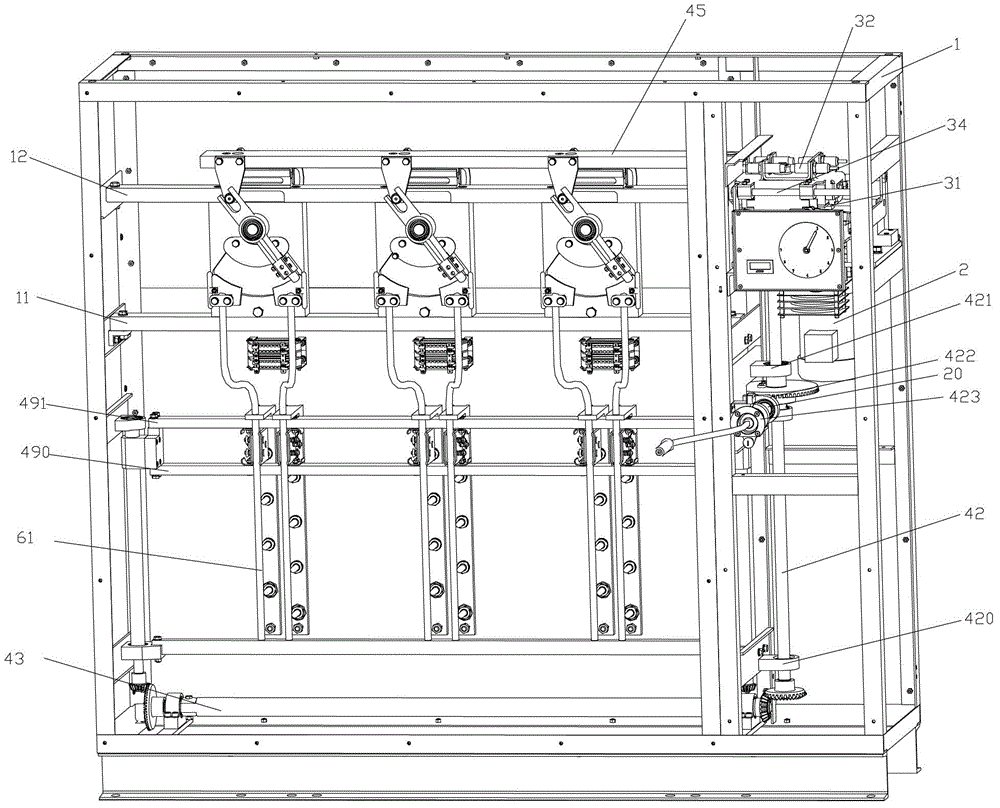
[0040] Such as figure 1 As shown, the vacuum on-load tap-changer described in this embodiment mainly includes the following four parts: (1) frame; (2) power drive mechanism; (3) vacuum bubble switching mechanism; (4) transformer winding tap position Adjustment device. The above four parts are described in detail below.

[0041] The first is the rack section, such as figure 1 As shown, the above-mentioned mechanisms and devices are all arranged in the frame 1, and the frame 1 is provided with two beams 11, 12 up and down. Three insulating blocks are evenly distributed between the two crossbeams to form a fixed frame of the switching mechanism. Specifically, two vacuum bubbles are installed on the rear side of each insulating block, arranged side by side. combine Figure 7 , There is an insulating bottom plate on the back of the rack, on which are installed 3 sets of vertical fixed contact mounting frames, each group of fixed contact mounting frames is composed of two insul...


PUM


Abstract

The invention discloses a vacuum on-load tap changer which comprises a rack, a power driving mechanism, three vacuum envelope switching mechanisms and a transformer winding tap position adjustment device, wherein the power driving mechanism is arranged above one side of the rack, controls a skateboard to perform horizontal stepped movement quickly, and drives the transformer winding tap position adjustment device to move through a driving shaft; each vacuum envelope switching mechanism comprises a shifting fork, a gauge finder and two vacuum envelopes; each shifting fork is driven by the skateboard, and then drives each gauge finder to rotate to drive every two vacuum envelopes to be switched vertically by turns; the transformer winding tap position adjustment device comprises two screw rods, an insulation shaft and two insulation cross beams mounted on nuts of the screw rods; the insulation shaft is driven by the driving shaft to drive the two screw rods to rotate; and the nuts of the screw rods drive the two insulation cross beams to perform longitudinal movement to realize position adjustment of a transformer winding tap. The tap changer has the advantages of low cost, high safety, high precision and long service life.

Description

technical field [0001] The invention relates to the field of tap changer research, in particular to a vacuum on-load tap changer. Background technique [0002] The on-load tap-changer is used to change the transformation ratio by selecting different winding taps of the transformer under load conditions, so that the grid voltage, active power and reactive power can be adjusted in time. [0003] The patent application number WO00 / 24013 discloses a three-phase step switch, which is a step switch capable of uninterrupted switching between different winding taps of a step adjustable transformer, and only two vacuums are used for each phase The bubble is used as an electric switch device to realize the switching of the main and auxiliary circuits. This kind of step switch is provided with two rows of staggered and fixed selection contacts arranged side by side, which are respectively connected to the winding taps; the first drive shaft is driven by the unique drive motor to reali...

Claims


Application Information

Patent Timeline
Patent Type & Authority Applications(China)
IPC IPC(8): H01H1/56H01F29/04
Inventor 钟建华林广斌张文英
Owner GUANGZHOU DEPOSON ELECTRIC TECH
Why Eureka
Try Eureka