Special driving method of RS485 circuit in dual opto-isolator periphery application
A driving method and circuit technology, applied in the direction of logic circuit connection/interface layout, electrical components, electronic switches, etc., can solve the problems of enhanced driving ability, inability to add pull-up and pull-down resistors, and high cost, so as to reduce costs, reduce optocouplers and The effect of two pull-up and pull-down resistors
- Summary
- Abstract
- Description
- Claims
- Application Information
AI Technical Summary
Problems solved by technology
Method used
Image
Examples
specific Embodiment approach
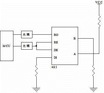
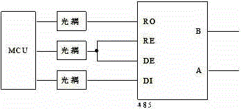
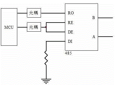
[0025] Such as Figure 4 Shown, be the work flowchart of the present invention, combine Figure 5 , a specific embodiment of the present invention is as follows: the counting time of the counter 4 can be adjusted according to specific needs. In this embodiment, the counting time of the counter 4 is set to be 10 μs. When the signal of the RE / DE port is "1", the RS485 circuit Enter the normal driver mode. In the normal driving mode, the RS485 circuit realizes the normal driving function; when the signal of the RE / DE port changes from "1" to "0", the control module 3 connected to the RE / DE port Make the RS485 circuit enter a special drive mode, and start counting through the counter 4 set in the RS485 circuit; in the special drive mode, the A port of the RS485 circuit outputs a drive signal that is inverse to the DI port, and the B port outputs a drive signal that is in phase with the DI port The signal, of course, can also be changed as needed so that the B port outputs a drivi...
PUM
 Abstract
Description
Claims
Application Information
 - R&D
- Intellectual Property
- Life Sciences
- Materials
- Tech Scout
- Unparalleled Data Quality
- Higher Quality Content
- 60% Fewer Hallucinations
Browse by: Latest US Patents, China's latest patents, Technical Efficacy Thesaurus, Application Domain, Technology Topic, Popular Technical Reports.
© 2025 PatSnap. All rights reserved.Legal|Privacy policy|Modern Slavery Act Transparency Statement|Sitemap|About US| Contact US: help@patsnap.com


