Door handle assembly for a vehicle

A technology of door handles and components, applied in the direction of vehicle locks, lock applications, connecting components, etc., can solve problems such as the lock cylinder can no longer be reached

Active Publication Date: 2013-10-02
AUDI AG
View PDF7 Cites 32 Cited by
  • Summary
  • Abstract
  • Description
  • Claims
  • Application Information

AI Technical Summary

Problems solved by technology

The disadvantage is that the handle body can no longer be moved when the motorized drive (device) fails, and thus the lock cylinder can no longer be reached

Method used


Image

  • Door handle assembly for a vehicle
  • Door handle assembly for a vehicle
  • Door handle assembly for a vehicle

Examples


Embodiment Construction

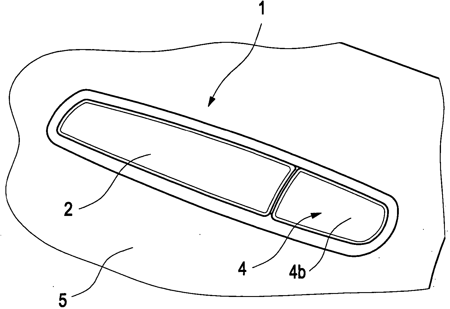
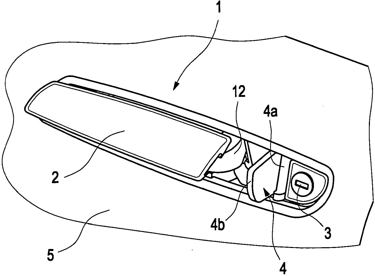
[0022] according to figure 1 and figure 2 , viewed from the outside of the vehicle, the door handle assembly 1 shows a door handle 2 that is flush with the body line and a side-by-side movable cover 4 that is flush with the body line, the movable cover includes a valve 4a and a Shutter 4b on the valve. The surface of the door handle 2 and the surface of the shutter 4b are in the same plane as the door 5 surrounding them. The shutter 4b covers the lock cylinder 3 below it in normal use, such as figure 1 shown. In special cases, especially when the action of bringing the door handle 2 from the rest position to the working position by external force fails, the movable cover plate 4 can be manually swung to expose the lock cylinder 3, so as to insert the mechanical key, and At the same time bring the door handle 2 into the working position, e.g. figure 2 shown.

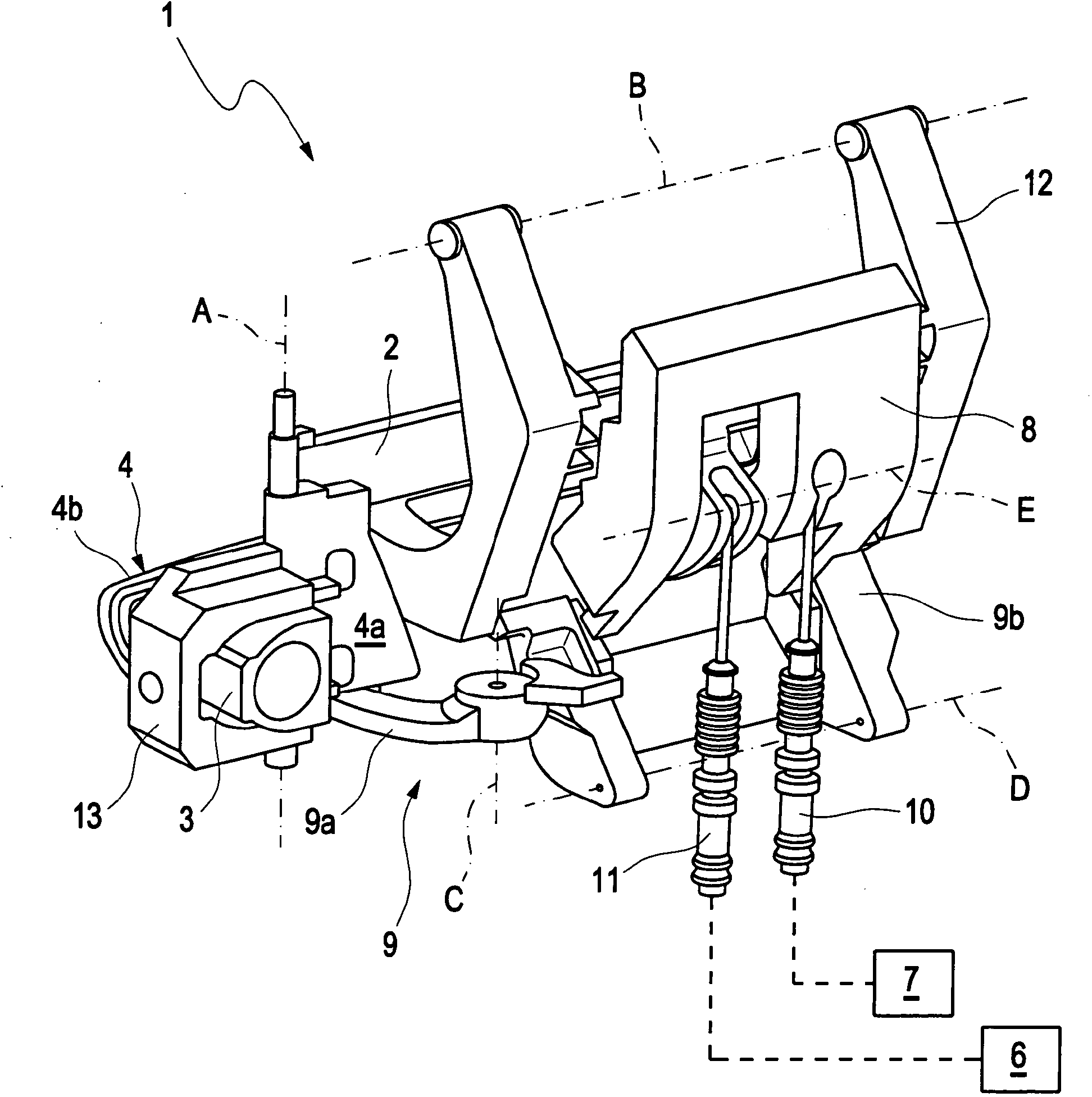
[0023] according to image 3 and Figure 4 , the door handle assembly 1 viewed from its rear side shows the d...


PUM


Abstract

Door handle assembly (1) for a vehicle, comprising a door handle (2) for actuating a door lock (6), which door handle can be brought, actuated by an externally applied force, from a rest position in which it is flush with the outer contour of the door into an exposed working position, and a closing cylinder (3), coordinate with the door handle (2), for locking or unlocking the door lock (6). The closing cylinder (3) can be covered by a cover flap (4) the manual actuation of which releases the closing cylinder (4) and allows the door handle (2) to be brought from the rest position into the working position.

Description

technical field [0001] A door handle assembly for a vehicle, having a door handle for operating a door lock and a key cylinder for locking or unlocking the door lock arranged side by side with the door handle, the door handle being operable by external force from flush with the body line The (strakbündigen) rest position is brought / placed into the revealed working position. Background technique [0002] Such door handle assemblies are used in vehicles to open and close hoods or doors disposed in openings in the vehicle body. A door handle flush with the body line is a door handle whose surface in the rest position lies in a plane with the body part surrounding the door handle. In order for the door handle to be gripped by the user, the door handle must preferably be brought from the rest position into the exposed working position under external force actuation. [0003] Such a door handle assembly is disclosed in DE19731325A1. In this case, the handle part for opening the...

Claims


Application Information

Patent Timeline
Patent Type & Authority Applications(China)
IPC IPC(8): E05B65/20
CPCE05B85/103E05B85/107E05B85/18E05B81/77Y10T70/7051Y10T70/5978Y10T70/8649Y10T70/7102Y10T70/7955Y10T70/577Y10T70/7107Y10T292/57Y10T70/5761Y10T70/7559Y10S292/31E05B81/16E05B83/36
Inventor G·伯姆G·霍赫霍尔策
Owner AUDI AG
Why Eureka
Try Eureka