Siphon head used for cleaning swimming pool

A swimming pool and siphon head technology, applied in the field of siphon head, can solve the problems of small siphon force and the like

Active Publication Date: 2013-10-09
NINGBO DONGCHUAN SWIMMING POOL EQUIP
View PDF4 Cites 5 Cited by
  • Summary
  • Abstract
  • Description
  • Claims
  • Application Information

AI Technical Summary

Problems solved by technology

Also caused the siphon head in the prior art to have the defect that the siphon force is small all the time

Method used


Image

  • Siphon head used for cleaning swimming pool
  • Siphon head used for cleaning swimming pool
  • Siphon head used for cleaning swimming pool

Examples


Embodiment Construction

[0024] The present invention will be described in further detail below in conjunction with the accompanying drawings.

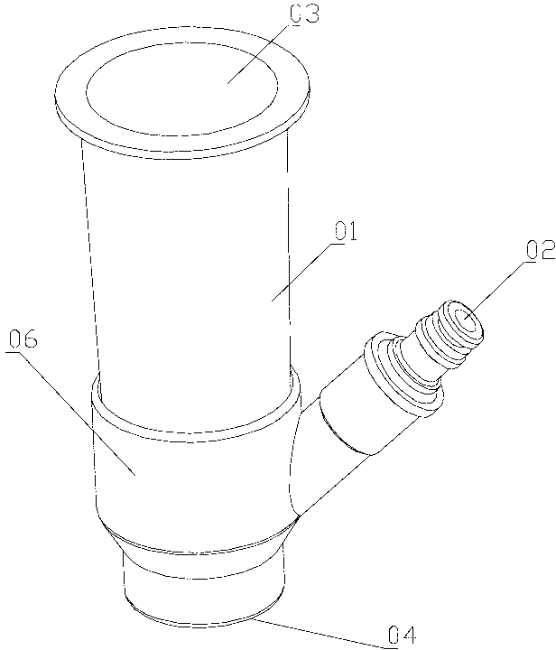
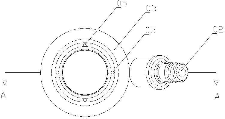
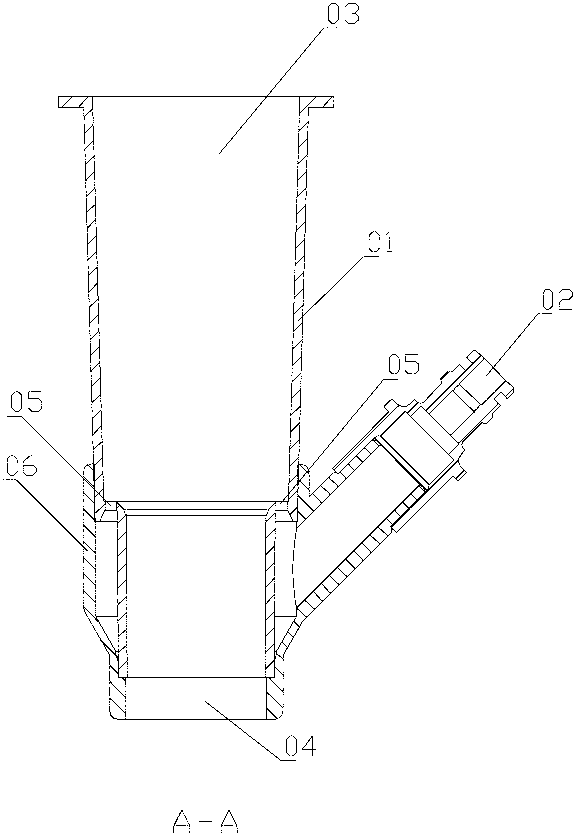
[0025] combined with Figure 7 to attach Figure 11 , a siphon head for cleaning swimming pools, which includes a cylinder 1, the upper end of the cylinder 1 is provided with a sewage outlet 3, the lower end is provided with a sewage suction port 4, and the side wall is provided with a water inlet 2; The water outlet 2 communicates with the inner cavity of the cylinder body 1 through the water outlet hole 5, and the water outlet direction of the water outlet hole 5 faces the sewage outlet 3; the cylinder body 1 is from the water outlet of the water outlet hole 5 to the sewage outlet. Port 3 has a closing structure that gradually becomes smaller. There is one sewage outlet 3, one water outlet 5, and the height difference H between the water outlet 5 and the sewage outlet 3 is between 120-140 mm; the area of ​​the horizontal section of the sewage outlet 3 is ...


PUM


Abstract

The invention provides a siphon head used for cleaning a swimming pool. The siphon head comprises a barrel (1), a dirt outlet (3) is formed in the upper end of the barrel (1), a dirt suction opening (4) is formed in the lower end of the barrel (1), and a water inlet (2) is formed in the side wall of the barrel. The water inlet (2) is communicated with an inner cavity of the barrel (1) through a water outlet hole (5), and the water outlet direction of the water outlet hole (5) faces toward the dirt outlet (3). The siphon head used for cleaning the swimming pool is characterized in that the barrel (1) is of a closing-in structure which gradually becomes small from a water outlet of the water outlet hole (5) to the dirt outlet (3).

Description

technical field [0001] The invention relates to a siphon head for cleaning swimming pools. Background technique [0002] In the prior art, there is a cleaner that uses the principle of siphon to clean the bottom of the swimming pool. It mainly includes two parts: a siphon head and a cleaning head. figure 1 to attach Figure 4 , the siphon head includes a cylinder 01, the upper end of the cylinder 01 is the sewage outlet 03, the lower end is the sewage suction port 04, and the lower part of the cylinder 01 is provided with an annular water conduction chamber 06, and the annular water conduction chamber 06 is provided with a plurality of water outlet holes 05, and the annular water guiding chamber 06 is also communicated with a water inlet 02. The water outlet holes 05 are evenly distributed on the upper end surface of the annular water conducting chamber 06 and are located in the cylinder body 01; the cleaning head includes a joint 07, a handle connection part 08 and a roll...

Claims


Application Information

Patent Timeline
Patent Type & Authority Applications(China)
IPC IPC(8): E04H4/16
Inventor 何怀忠
Owner NINGBO DONGCHUAN SWIMMING POOL EQUIP
Why Eureka
Try Eureka