Spiral winding pipe floating heat exchanger

A technology of floating head heat exchangers and spirally wound tubes, which is applied to the types of heat exchangers, heat exchanger shells, indirect heat exchangers, etc., which can solve the problems of inconspicuous heat exchange effects, small length of heat medium tube bundles, and unfavorable heat exchange Efficiency and other issues

Active Publication Date: 2013-10-09
HIMILE MECHANICAL MFG
View PDF10 Cites 18 Cited by
  • Summary
  • Abstract
  • Description
  • Claims
  • Application Information

AI Technical Summary

Problems solved by technology

Most of the heat exchangers currently used are equipped with straight-tube heat medium tube bundles. This kind of heat exchanger mainly has the following disadvantages: the heat medium tube bundle is limited by the tube length, so the length of the heat medium tube bundle is small, and the medium is in The flow in the straight pipe is uniform, so that the turbulence effect of the heat exchanger is poor, resulting in the inconspicuous heat transfer effect, which is not conducive to improving the heat transfer efficiency
Most of the above-mentioned heat exchangers are floating head heat exchangers. The floating head needs to be disassembled for tube bundle cleaning, which is inconvenient to clean, and there will be a certain force between the tube plate and the cylinder at the floating head end, which is not conducive to the long-term stable heat exchange operation of the heat exchanger.
The floating head structure also increases the difficulty of manufacturing the heat exchanger, and its cost also increases

Method used


Image

  • Spiral winding pipe floating heat exchanger
  • Spiral winding pipe floating heat exchanger
  • Spiral winding pipe floating heat exchanger

Examples


Embodiment Construction

[0026] Below in conjunction with accompanying drawing and embodiment, further elaborate the present invention. In the following detailed description, certain exemplary embodiments of the invention are described by way of illustration only. Needless to say, those skilled in the art would realize that the described embodiments can be modified in various different ways, all without departing from the spirit and scope of the present invention. Accordingly, the drawings and description are illustrative in nature and not intended to limit the scope of the claims.

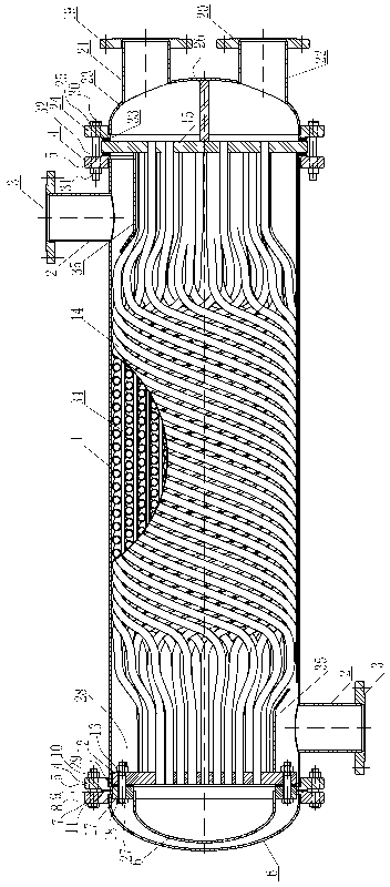
[0027] Such as figure 1 As shown, the spiral wound tube floating head heat exchanger includes a heat exchanger shell 1, and the heat exchanger shell 1 includes a shell-side connecting pipe 2 arranged on the heat exchanger shell 1, and the shell-side The connecting pipe 2 is provided with a shell-side connecting flange 3, and the shell-side connecting flange 2 and the shell-side connecting flange 3 are respectively arra...


PUM


Abstract

The invention discloses a spiral winding pipe floating heat exchanger. The spiral winding pipe floating heat exchanger comprises a heat exchanger shell. A first shell end enclosure device and a second shell end enclosure device are arranged at the two ends of the heat exchanger shell respectively, and a heat exchanger core which can be drawn out of the heat exchanger shell is packaged in the heat exchanger shell; the second shell end enclosure device can be dismounted from the heat exchanger shell, therefore, the heat exchanger core and a channel end enclosure connected with the heat exchanger core can be drawn out of the heat exchanger shell, and heat exchange tubes can be maintained and cleaned conveniently. The spiral winding pipe floating heat exchanger is simple in structure and convenient to operate. A floating tube plate, a channel end enclosure flange and the channel end enclosure can move along with expansion caused by heat and contraction caused by cold of a tube bundle layer in the heat exchanger shell, and therefore pulling force and pushing force of the heat exchange tubes on the channel end enclosure and the second shell end enclosure device can be eliminated; the spiral tube bundle layer is beneficial to improving work stability of the heat exchanger, the structure enhances the turbulence effect greatly when fluid flows in the heat exchange tubes, and therefore heat exchange coefficients are improved.

Description

technical field [0001] The invention relates to the field of heat exchangers, in particular to a shell-and-tube heat exchanger with spirally wound tubes. Background technique [0002] The heat exchanger is a device that uses the medium in the tube side and the shell side for heat exchange. At present, the commonly used heat exchangers are mostly plate and tube, and the shell and tube heat exchanger has a wide range of application pressure and stability. The advantages of simple manufacture are widely used, especially in fields such as petroleum, chemical industry and printing and dyeing. Most of the heat exchangers currently used are equipped with straight-tube heat medium tube bundles. This kind of heat exchanger mainly has the following disadvantages: the heat medium tube bundle is limited by the tube length, so the length of the heat medium tube bundle is small, and the medium is in The flow in the straight pipe is uniform, so that the turbulence effect of the heat excha...

Claims


Application Information

Patent Timeline
Patent Type & Authority Applications(China)
IPC IPC(8): F28D7/10F28F9/06F28F9/013
Inventor 许倍强卢恩明唐立星雷伟
Owner HIMILE MECHANICAL MFG
Why Eureka
Try Eureka