A test device and method for steel-soil interface shear characteristics considering the thickness of the shear band

A characteristic test and shear band technology, which is applied in the direction of using a stable shear force to test the strength of materials, etc., can solve problems such as damage to the contact surface of steel and soil, and achieve the effect of ensuring high precision

Inactive Publication Date: 2016-06-08
CHONGQING JIAOTONG UNIVERSITY
View PDF3 Cites 0 Cited by
  • Summary
  • Abstract
  • Description
  • Claims
  • Application Information

AI Technical Summary

Problems solved by technology

[0005] However, there are still the following shortcomings in the prior art that have not been resolved: ① The steel-soil contact surface is artificially defined as the failure surface

Method used


Image

  • A test device and method for steel-soil interface shear characteristics considering the thickness of the shear band
  • A test device and method for steel-soil interface shear characteristics considering the thickness of the shear band
  • A test device and method for steel-soil interface shear characteristics considering the thickness of the shear band

Examples


Embodiment 1

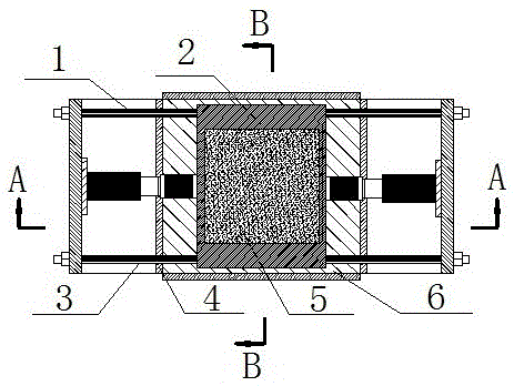
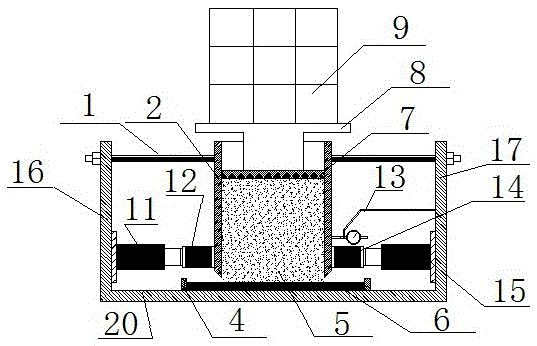
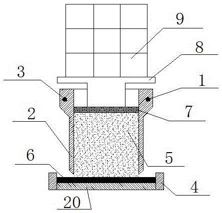
[0033] A test device for steel-soil interface shear characteristics considering the thickness of the shear zone, comprising a shear box 2, a bottom plate 20 and a pad 18. The bottom plate 20 has a horizontal upper surface carrying the steel plate 6 to be tested, and the shear box 2 has a hollow cavity for accommodating the soil sample 5 to be tested. It also includes a guide rail I1 and a guide rail II3 fixed above the bottom plate 20 and parallel to each other. The guide rail I1 and the guide rail II3 pass through the upper end of the shear box 2 , and the lower end of the shear box 2 is suspended, that is, the guide rail I1 and the guide rail II3 bear the weight of the shear box 2 . When the steel plate 6 to be tested is placed on the bottom plate 20 , there is a gap between the lower end of the shear box 2 and the upper surface of the steel plate 6 to be tested. The spacer 18 is filled in the gap.

[0034] In this embodiment, there are various ways to fix the guide rail I...

Embodiment 2

[0041] The method that adopts the device described in embodiment 1 to test may further comprise the steps:

[0042] 1) Fix the steel plate 6 to be tested on the horizontal upper surface of the bottom plate 20 . In this embodiment, several side limiting plates 4 can be installed on the upper surface of the bottom plate 20 (generally conveniently installed at both ends of the steel plate 6 to be tested) to prevent the steel plate 6 to be tested from sliding along the direction of the guide rail during the test. Further, the thickness of the side limiting plate 4 is greater than the thickness of the steel plate 6 to be tested, the purpose is to limit the movement of the spacer 18 during the sample preparation process. That is, the pad strip 18 is supported on the side limiting plate by a rigid rod, so as to avoid the wedge-shaped pad being extruded by the sample during the sample preparation process;

[0043] 2) Place the spacer 18 on the upper surface of the steel plate 6 to be...


PUM


Abstract

The purpose of the invention is to provide a steel-soil interface shear characteristic testing device and method considering the thickness of the shear band. The apparatus includes a shear box, a base plate and spacers. The base plate has a horizontal upper surface carrying the steel plate to be tested, the shear box has a hollow cavity for containing the soil sample to be tested, and also includes guide rails I and II fixed above the base plate and parallel to each other. When the steel plate to be tested is placed on the bottom plate, there is a gap between the lower end of the shear box and the upper surface of the steel plate to be tested. The spacer is filled in the gap. The test using the above device includes the following steps: 1) Fix the steel plate to be tested; 2) Insert the gasket into the gap; 3) Load the soil sample to be tested into the shear box; 4) Pull out the gasket; Apply a horizontal load parallel to the guide rail and reverse, and shear failure occurs at the steel-soil interface; 6) Apply a horizontal load in the opposite direction to step 5) on the shear box; 7) Repeat steps 5) and 6) several times.

Description

technical field [0001] The invention relates to the field of mechanical parameter measurement of material contact interface, in particular to the test of shear characteristic of steel-soil interface in civil engineering. Background technique [0002] With the prosperity of the inland waterway shipping industry, the construction tasks of mountainous river ports and wharves are heavy. In order to meet the requirements of modern wharf construction under the complex hydrogeological conditions of mountainous rivers, the deep-water wharves under construction or newly built in the western mountainous areas have widely adopted overhead and upright structures, and the pile foundations have just adopted large-size steel casing rock-socketed piles. The bearing capacity of the pile foundation is provided by the pile side resistance and the pile tip resistance. The essence of the pile foundation side friction resistance (including negative friction resistance) is the shearing effect of t...

Claims


Application Information

Patent Timeline
Patent Type & Authority Patents(China)
IPC IPC(8): G01N3/24
Inventor 梁越王俊杰刘明维刘楠楠
Owner CHONGQING JIAOTONG UNIVERSITY
Why Eureka
Try Eureka